LED Strip and Cabinet Lighting Safety Before Installation
LED strip and cabinet lighting safety depends on matched power, controlled heat, protected wiring, stable mounting, and suitable operating conditions. LED strip lighting can be used safely in many home cabinet areas when the power supply, connectors, cable route, surface, and airflow are checked before installation, but safety remains conditional on component fit, condition, load, and environment.
LED strip and cabinet lighting safety before installation means checking the full low voltage setup before the strip is fixed, hidden, or powered for regular use. The safety frame includes the LED tape, driver, connector, channel, cabinet surface, cable routing, and warning signs such as loose contact, damaged insulation, unusual heat, buzzing, flicker, or unstable mounting. These checks keep the article focused on pre-installation judgment, not on product selection, repair, or full installation steps.
Start the safety check by matching the strip, controller, and power supply before mounting. Then check heat control, wiring protection, connector seating, cabinet surface condition, cable movement, and airflow. If mains wiring, hidden wiring, or unclear electrical conditions are involved, a qualified electrician should handle that part before the cabinet lighting setup is used.
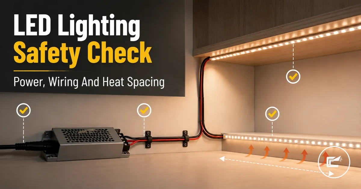
LED Strip and Cabinet Lighting Safety Before Installation needs one visual checkpoint before the detailed checklist sections begin. The image should label the main safety checkpoints: the LED strip, cabinet surface, power supply, connector, cable routing, and airflow or channel support.
When LED strip and cabinet lighting is safe
LED strip and cabinet lighting is generally safe when the kit, power supply, wiring, mounting, and operating environment are compatible and undamaged. Safe use is conditional because voltage, load, heat, connector integrity, surface condition, moisture exposure, and usage duration can affect the level of risk. LED strip and cabinet lighting remains safer when these parts work together as intended and stay in suitable condition.
In this context, home LED strip and cabinet lighting accessories are the parts that support the lighting system during normal use. The setup should remain low voltage, use components rated for the connected load, and stay mounted on a suitable surface. A dry and protected environment can help reduce avoidable stress on connectors, wiring, and cabinet light components.
Low voltage can reduce certain electrical hazards, but it does not make LED strip and cabinet lighting risk-free. Low-voltage accessories can still experience overheating, a short, loose connections, or component failure when they are poorly mounted, mismatched, damaged, or exposed to unsuitable environmental conditions.
When LED strip and cabinet lighting is safe, the checklist below verifies the main conditions that support safe operation and highlights conditions that may increase risk.
- Check that the LED strip or cabinet light voltage is compatible with the connected power supply and accessories.
- Confirm that the connected load is suitable for the rated driver and operating setup.
- Inspect connectors for secure, undamaged contact and signs of wear.
- Verify that the lighting is mounted on a stable surface with reasonable airflow around the strip, channel, or cabinet light.
- Keep wiring protected from moisture, sharp edges, moving parts, and physical strain.
- Watch for warning signs such as unusual heat, flicker, loose mounting, damaged insulation, buzzing, or a burning smell.
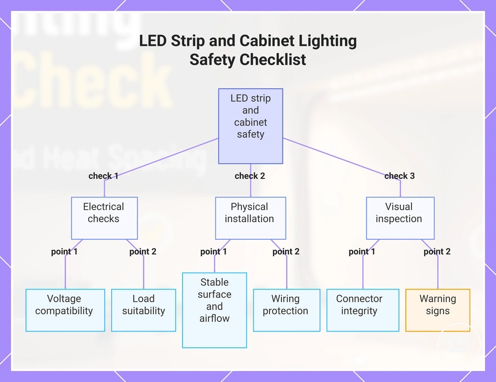
This chart shows the main checks and warning signs for safe operation of LED strip and cabinet lighting.
Fire and overheating risk checks
Fire and overheating risk increases when heat buildup, overloaded components, poor contact, unsuitable surfaces, moisture, covering, or damaged accessories are present. Heat, overload, and damaged parts directly increase risk, while actual fire outcomes depend on how these conditions develop and whether warning signs are addressed. Fire and overheating risk checks help identify conditions that may lead to overheating or create a fire hazard during use.
Fire and overheating risk can come from high LED strip density, excessive power load, limited ventilation, exposed contact points, damaged insulation, or a driver operating beyond its intended capacity. Aluminum channel support can help manage heat, while enclosed spaces may trap heat and reduce airflow. Moisture exposure can contribute to corrosion, poor contact, or a short circuit. Discoloration, unusual heat, or visible damage can indicate an unsafe condition.
Fire and overheating risk checks are easier to understand when the main heat sources and risk points are visible. The image below labels conditions related to heat buildup, enclosure, airflow, and nearby material exposure.
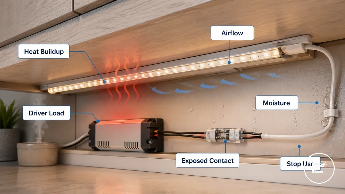
Fire and overheating risk checks organize the conditions that increase temperature or ignition risk and help identify situations that may require correction before continued use.
- Check for heat buildup around LED strips, drivers, channels, and enclosed cabinet spaces.
- Confirm that ventilation is not blocked by coverings, stored items, insulation, or tight enclosures.
- Inspect for exposed contact points, loose connections, damaged insulation, or signs of a short circuit.
- Look for overload indicators such as unusual heat from plugs, drivers, connectors, or related accessories.
- Assess whether mounting surfaces are stable, dry, and free from conditions that may increase heat retention.
- Review under-cabinet areas where heat, steam, moisture, and enclosure can combine and increase risk.
- Watch for discoloration, odor, deformation, melting, or recurring flicker that may signal overheating.
- Stop use if components become unusually hot, show visible damage, or display other warning signs of an unsafe condition.
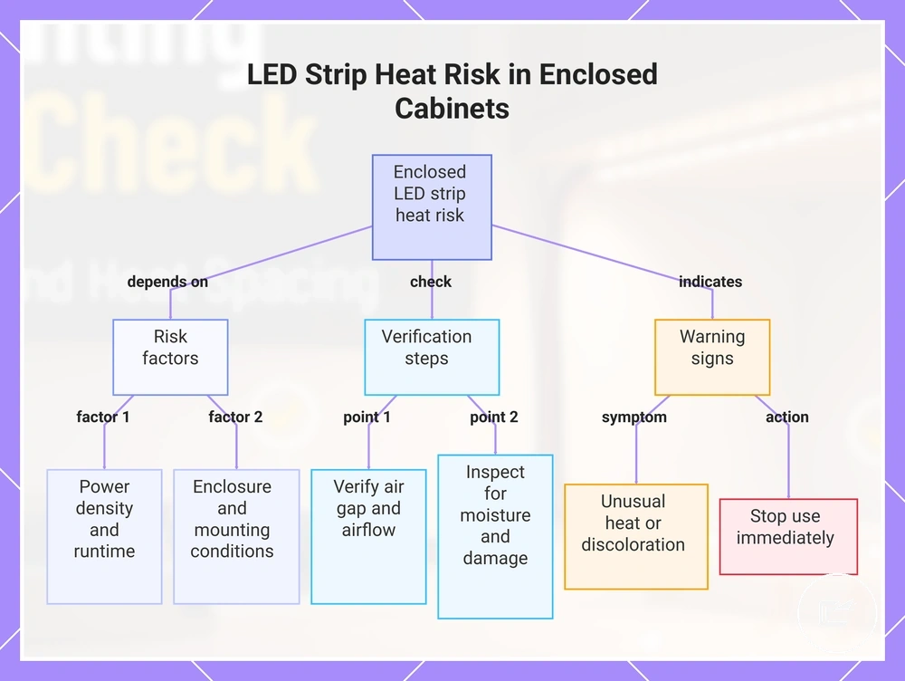
Heat dissipation and enclosed cabinet conditions
LED strips in enclosed cabinet conditions can experience greater heat buildup when ventilation is limited. Risk depends on strip power density, runtime, enclosure depth, nearby objects, air gap availability, and the mounting surface. An aluminum mounting surface may help with heat dissipation in some installations, while LED strips placed inside cabinets, under shelves, or behind diffusers with restricted airflow may face a higher risk of overheating over time.
Heat dissipation and enclosed cabinet conditions can be checked with these enclosure-specific factors:
- Verify that an air gap remains around the LED strip, diffuser, or channel where airflow is available.
- Check whether nearby objects, shelf panels, or cabinet contents reduce ventilation around the strip.
- Consider whether long runtime periods may allow additional heat buildup inside the enclosure.
- Inspect enclosed areas for moisture, damaged components, or exposed contact points that may contribute to an unsafe condition.
- Stop use if unusual heat, discoloration, or other signs of overheating appear during operation.
This chart shows the key factors that contribute to heat buildup in enclosed LED strips, the verification checks to perform, and the warning signs that require immediate action.
Flammable surfaces, covering, and moisture exposure
Surface, covering, and moisture exposure can increase risk even when LED strip lighting operates normally. Wood, laminate, paper lining, fabric, plastic film, adhesive backing, steam, and moisture can change operating conditions and may contribute to overheating, a fire hazard, or an unsafe condition when ventilation is reduced or components become damaged. Moisture-rated products and careful placement may help reduce risk in suitable locations, but they do not remove concerns related to damaged insulation or exposed contact points.
Flammable surfaces, covering, and moisture exposure checks group local conditions by risk type:
- Surface check: Review wood, laminate, paper lining, fabric, and similar nearby materials that may be exposed to ongoing heat buildup.
- Covering check: Confirm that covered strips are not blocked by plastic film, fabric, stored items, or other materials that may reduce ventilation.
- Adhesive check: Inspect adhesive backing for lifting, damage, or movement that could change strip position.
- Moisture check: Look for steam exposure near sink areas and signs of moisture around the installation location.
- Contact check: Inspect for exposed contact points, damaged insulation, or conditions that may contribute to a short circuit.
- Stop-use check: Stop use if moisture reaches exposed contacts or if visible damage creates an unsafe condition.
Power supply and low-voltage safety checks
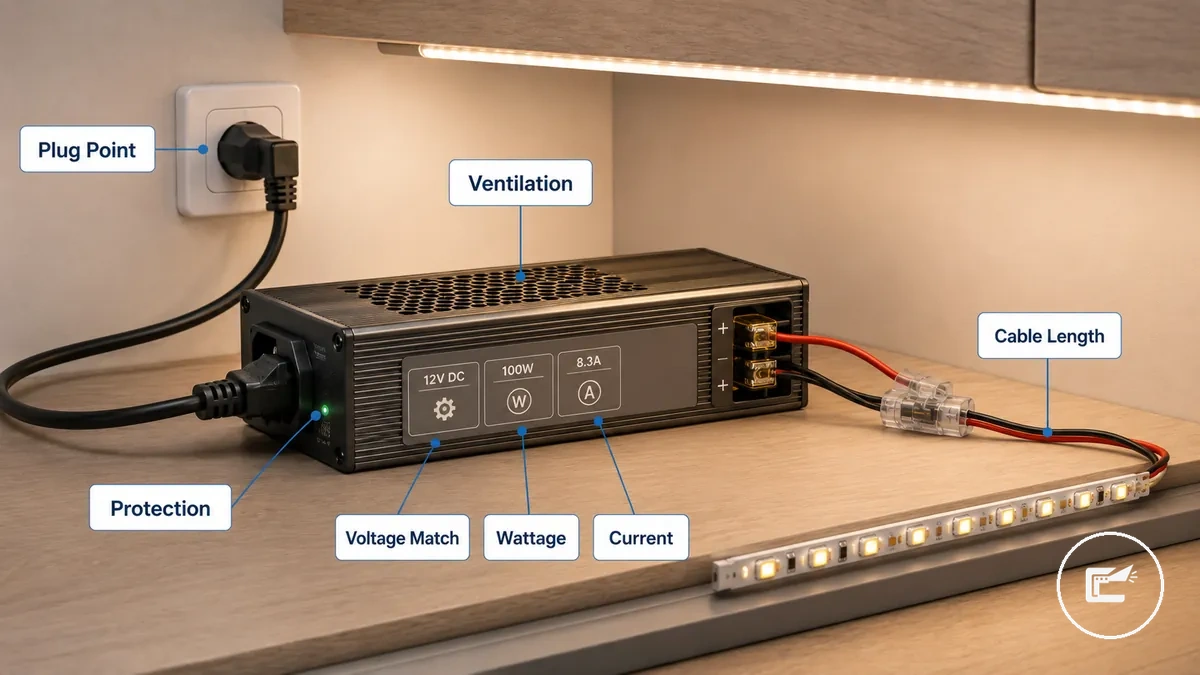
Power supply and low-voltage safety checks depend on matching voltage, sufficient wattage capacity, an appropriate current rating, protection features, plug condition, and the installation environment. Voltage must match the connected lighting system, and overload conditions should be avoided. Low voltage can reduce certain electrical risks, but safe operation still depends on component condition, ventilation, moisture exposure, and protection against damage.
A power supply, driver, plug point, and low-voltage circuit should be checked as a connected system. Voltage mismatch can create an unsafe condition, while inadequate wattage capacity, poor ventilation, excessive cable length, or a damaged plug may contribute to flicker, overheating, or failure depending on load and operating conditions. Exposed contact points, moisture, or damaged insulation can increase risk and may require the system to be taken out of service until the condition is addressed.
Power supply and low-voltage safety checks organize the main electrical attributes by required condition and potential risk. Reviewing power supply compatibility can help verify whether connected ratings and operating conditions align before regular use.
Power supply and low-voltage safety checks are easier to review when voltage, wattage, driver, plug point, and protection checkpoints are labeled visually. The image below highlights the main conditions that should be verified before continued operation.
| Attribute | Required Condition | Risk if Ignored |
|---|---|---|
| Voltage | Matches the lighting system rating | Unsafe operation or component failure |
| Wattage Capacity | Supports the connected load | Overheating or unstable performance |
| Current Rating | Suitable for the operating setup | Potential overload conditions |
| Protection Features | Present and undamaged | Reduced protection during faults |
| Certification | Clearly identified and intact | Reduced confidence in product verification |
| Plug Point | Dry, secure, and free from damage | Unsafe condition or intermittent operation |
| Ventilation | Allows airflow around the driver or power supply | Heat buildup and possible overheating |
| Cable Length | Appropriate for the installation | Performance issues that may vary by setup |
Plug-in power supplies can often be checked visually for damaged cables, exposed contact points, moisture, or loose connections. Stop use if visible damage, unusual heat, or signs of a short circuit are present. Hardwired installations or unclear electrical conditions should be assessed by a qualified electrician rather than treated as a routine user check.
12V and 24V voltage matching
LED strip, controller, dimmer, and power supply compatibility depends on voltage matching before connection. A 12V LED strip must be used with a 12V power supply, controller, dimmer, and connector path, while a 24V LED strip must remain within the 24V voltage family. Mixed voltage ratings may cause failure, overheating, or unsafe performance depending on component configuration and protection features.
12V and 24V voltage matching can be checked by comparing the strip label, driver output, dimmer rating, connector rating, and extension cable suitability before use. These local checks help confirm that connected components share the same voltage family within the parent power-supply safety framework.
| Check Item | Required Match |
|---|---|
| LED Strip Label | 12V to 12V or 24V to 24V |
| Power Supply Output | Matches strip voltage |
| Controller Rating | Matches voltage family |
| Dimmer Rating | Compatible with strip voltage |
| Connector Rating | Suitable for the selected voltage |
| Extension Cable | Suitable for the connected voltage setup |
Wattage load, current rating, and safety margin
Load calculation depends on strip length, watts per meter, and the capacity of the connected driver. Total wattage increases as strip length increases, so the power supply and accessories should support the expected power draw. Current rating and available capacity should be checked together because overload conditions may contribute to overheating or unstable operation. A safety margin can provide safety headroom, but the appropriate margin depends on product ratings, operating conditions, and installation factors.
Wattage load, current rating, and safety margin can be reviewed with a simple calculation flow that organizes load by strip length, wattage, and margin.
- Measure strip length.
- Identify watts per meter from the strip specification.
- Calculate total watts: strip length × watts per meter.
- Compare total watts with driver capacity and current rating.
- Allow a reasonable safety margin based on the equipment and operating conditions.
- Example: a 5-meter strip rated at 10 watts per meter creates a total load of 50 watts before any additional safety headroom is considered.
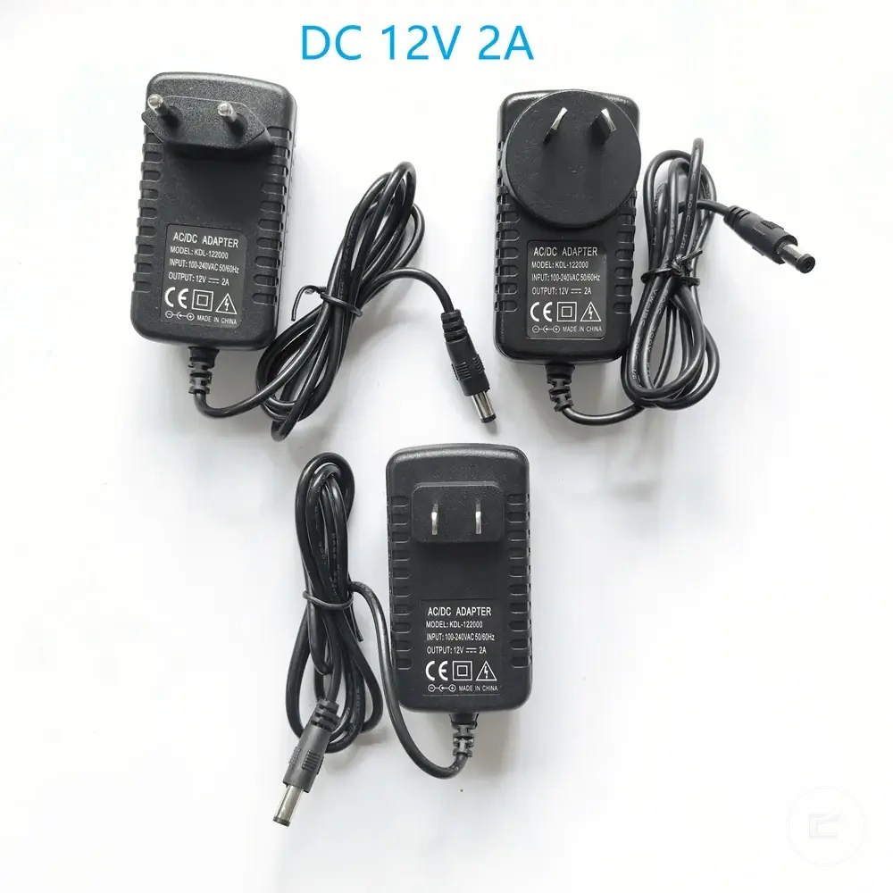
Protected drivers and safe plug points
Protected drivers and safe plug points reduce risk when they are dry, ventilated, undamaged, and suitable for the connected load. A protected driver can help reduce overload or short circuit risk when its protection features are intact, while a secure plug point helps reduce loose contact, overheating, and damaged cord risks. Damaged or poorly ventilated power parts should not be used.
The driver and outlet should be checked as separate safety checkpoints before continued use:
- Check that overload protection and short-circuit protection are not bypassed or visibly damaged.
- Keep the driver and plug point dry, accessible, and away from moisture exposure.
- Allow ventilation around the driver so heat buildup is less likely during operation.
- Inspect the cord for cuts, crushed insulation, exposed contact points, or visible damage.
- Confirm that the plug fits securely without looseness, buzzing, or repeated tripping.
- Keep switching accessible so the lighting can be turned off quickly if an unsafe condition appears.
- Stop use if there is a burning smell, repeated tripping, buzzing, overheating, or visible damage.
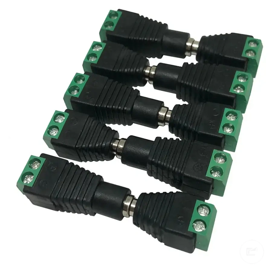
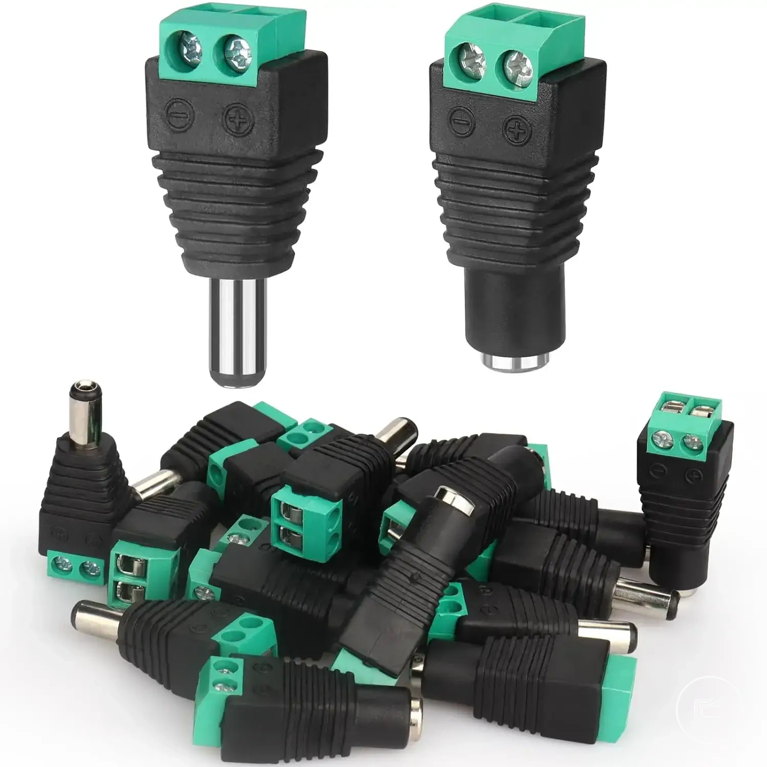
Wiring and connector safety checks
Wiring and connector safety depends on clean contact, correct polarity, intact insulation, secure routing, and protection from strain or pinch points. Exposed contacts and loose connectors require attention before use because they may contribute to flicker, short circuit conditions, overheating, or component failure. Safe wiring depends on both electrical contact quality and physical cable protection.
Wiring and connector safety checks identify contact and routing conditions that may create risk. The image below labels connector contact, polarity, insulation, cable routing, and pinch-risk areas that should be inspected before continued use.
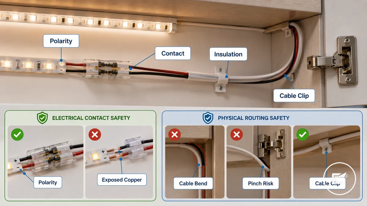
Wiring and connector safety checks should separate electrical contact risks from physical routing risks. Connector polarity should match the intended connection, contact pressure should remain secure, and insulation should cover conductors without exposed copper. Connector and cable current ratings should be suitable for the connected circuit. A connector that works during testing may become an unsafe condition when the cable is pulled, bent repeatedly, or trapped behind cabinet hardware. Moisture, damaged insulation, or poor ventilation around enclosed cable routes may increase the likelihood of heat buildup.
Wiring and connector safety checks organize the main inspection points that help identify contact and routing issues before continued use.
- Check connector polarity before powering the lighting system.
- Inspect contact pressure and confirm that connectors remain firmly seated.
- Look for damaged insulation, exposed contact points, or exposed copper.
- Verify that connector and cable current ratings are suitable for the intended connection.
- Check cable bends for excessive stress that may affect contact quality over time.
- Use cable clips or similar support to reduce strain and unwanted movement.
- Keep cable routes away from pinch points, hinges, drawers, and moving hardware.
- Stop use if wiring becomes damaged, connectors loosen, or signs of overheating appear.
For more detailed guidance on routing and managing cables, see safe wiring and connections.
Wire gauge, insulation, and exposed contact risks
Wire gauge, insulation condition, and exposed contact points affect risk because heat buildup, short circuit conditions, and overheating can depend on how current, insulation, and connector fit interact. Wire gauge should be suitable for the connected circuit, while insulation should remain intact without cuts, cracks, or damaged sections. Exposed copper, loose terminals, or poor connector fit may create an unsafe condition, especially when moisture or limited ventilation is present. Connector fit and polarity marks should remain clear and secure so contact quality is maintained.
Wire gauge, insulation, and exposed contact risks can be checked through these local inspection points:
- Inspect wire gauge and current rating for suitability within the connected setup.
- Look for damaged insulation, cuts, cracks, or areas where conductors may be exposed.
- Check for exposed copper, loose terminals, or exposed contact points.
- Verify that polarity marks remain visible and connectors fit securely onto strip contacts.
- Stop use if bare copper, melted insulation, or connectors that do not fully grip strip contacts are present, as these conditions may increase short circuit or fire hazard risk.
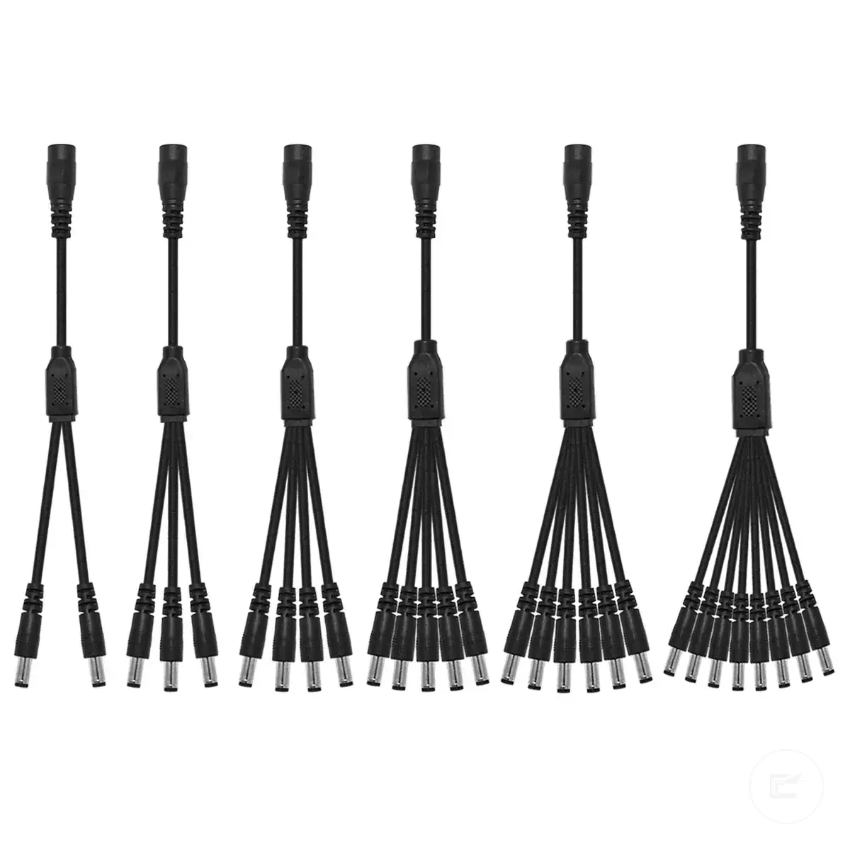
Cable routing, strain relief, and pinch points
Cable routing starts with a cable path that reduces tension, rubbing, cabinet-door pinching, and accidental pulling after mounting. Routing should keep the cable supported along a stable surface, while clips and strain relief help reduce movement at connection points. A cable route that appears safe when a cabinet door is open may become unsafe after repeated door or drawer movement. Adhesive-supported cable placement should also be checked because support conditions can change over time.
Cable routing, strain relief, and pinch points can be checked with this routing checklist that verifies cable movement and pressure points:
- Check that the cable route follows a stable surface without unnecessary tension.
- Inspect clips and strain relief points for secure support without excessive pressure on the cable.
- Review corner turns to confirm the cable path is not sharply bent.
- Check hinge zones where cabinet-door movement may pinch or rub the cable.
- Inspect drawer movement areas where repeated opening and closing may affect cable placement.
- Look for sharp edges that may damage insulation through contact over time.
- Check hidden gaps where the cable may become trapped during normal cabinet use.
- Correct pinched or strained cable paths before use because movement and pressure conditions may change after installation.
Mounting and airflow checks under cabinets
Mounting and airflow checks under cabinets help reduce risk from heat buildup, unstable placement, blocked ventilation, and unsafe material contact. A stable mounting surface and adequate airflow can help limit overheating, while poor adhesion or restricted ventilation may increase detachment risk or create an unsafe condition. Under-cabinet installations should be checked because cabinet layout, enclosure, and surface condition can affect both support and heat management.
Mounting surface condition, channel support, clip spacing, and air gaps work together to influence stability and ventilation. A clean, heat-resistant surface may improve adhesion, while moisture, grease, or damaged surfaces can reduce support over time. In under-cabinet kitchens, steam, grease, and enclosure conditions may affect adhesion and airflow, especially when channels, clips, or nearby objects limit ventilation around the lighting.
Mounting and airflow checks under cabinets organize surfaces, channels, clips, and air gaps by their safety effect.
| Condition | Supports Safer Operation | May Increase Risk |
|---|---|---|
| Mounting Surface | Clean, stable, and suitable for adhesion | Dirty, greasy, moist, or damaged surface |
| Heat Resistance | Surface remains suitable near normal operating heat | Unsafe material contact or fire hazard risk |
| Channel Support | Provides stable support and spacing | Loose or unstable placement |
| Clip Spacing | Supports consistent mounting | Movement or falling sections |
| Air Gap | Allows ventilation around the lighting | Blocked airflow and heat buildup |
| Nearby Obstructions | Open space around the installation | Enclosure, stored items, or restricted ventilation |
Blocked airflow and unstable mounting should be corrected before continued use. If mounting materials become damaged, ventilation is restricted, or exposed contact points appear after movement or detachment, stop use and inspect the installation. For broader placement guidance, see the installation steps.
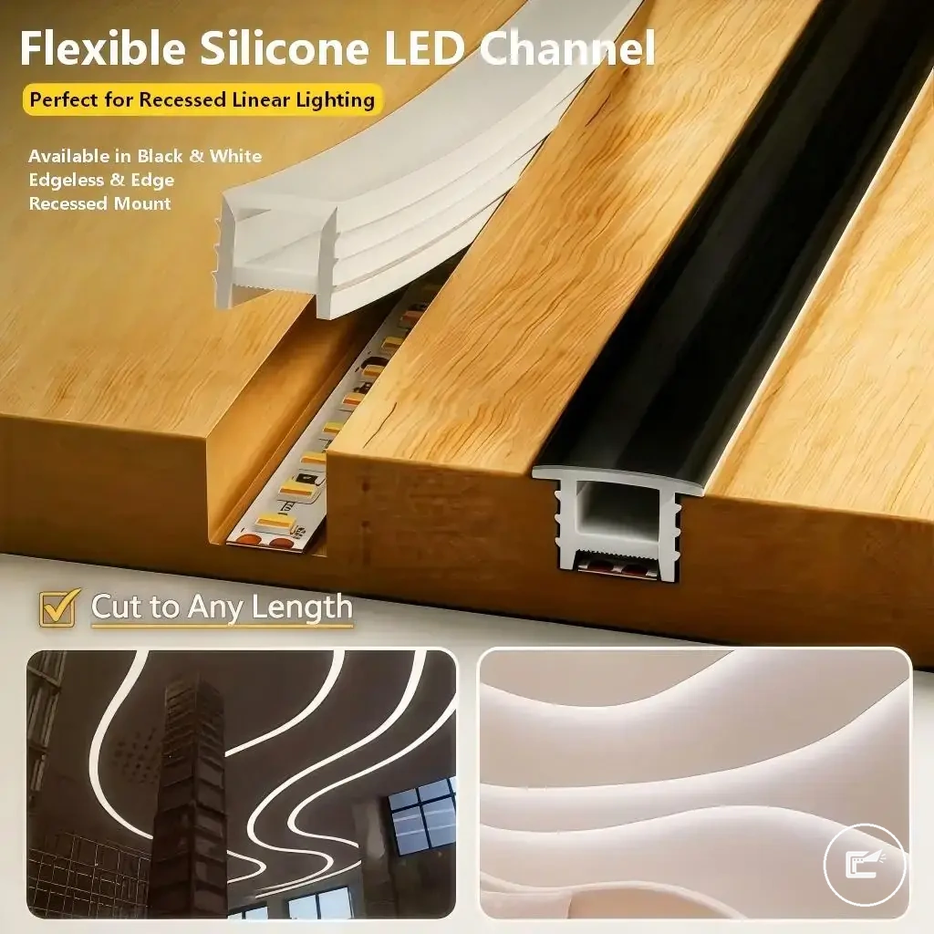
Aluminum channels and heat-spreading support
An aluminum channel can support heat spreading, strip protection, diffuser placement, and cleaner mounting when the profile fits the LED strip and cabinet surface. The channel should not be treated as automatic protection because heat behavior depends on strip fit, surface contact, airflow, and the surrounding air gap. A diffuser can help cover and protect the strip, but decorative covering is different from heat-spreading support.
Aluminum channels and heat-spreading support depend on these channel attributes:
- Check that the aluminum channel material supports stable mounting and contact with the strip backing.
- Verify that channel width and depth allow the strip and diffuser to fit without pressure or poor contact.
- Confirm that the diffuser cover sits correctly without trapping heat in a tight enclosure.
- Review the mounting method so the channel stays secure on the cabinet surface.
- Leave an air gap where possible so ventilation is not fully blocked.
- Check heat contact between the strip and channel, because poor contact may reduce heat spreading support.
Adhesive surfaces, cable clips, and stable placement
Stable placement starts with secure mounting, reliable routing, and mechanical support that helps prevent strips or wires from sagging, detaching, or contacting unsafe surfaces. Adhesive surface condition, cable clips, and placement stability should be checked because support performance may vary with surface texture, cleanliness, heat exposure, and cabinet movement. Loose or sagging placement should be corrected before use because shifting cables can create a pinch point, reduce strain relief, or place wiring against unsuitable surfaces.
Adhesive surfaces, cable clips, and stable placement depend on surface preparation and mechanical support:
- Check that the mounting surface is clean and free from contamination that may reduce adhesive support.
- Inspect surface texture because rough or uneven areas may affect placement stability.
- Review heat exposure around the mounting area because adhesive performance can vary with operating conditions.
- Look for lifting, cracking, or damaged adhesive that may indicate reduced support.
- Verify that clips provide cable support without excessive pressure on the cable path.
- Check clip spacing so routing remains supported along the cabinet surface.
- Inspect strip bend points for tension that may affect mounting or strain relief.
- Review cabinet vibration or repeated movement that may contribute to gradual detachment over time.
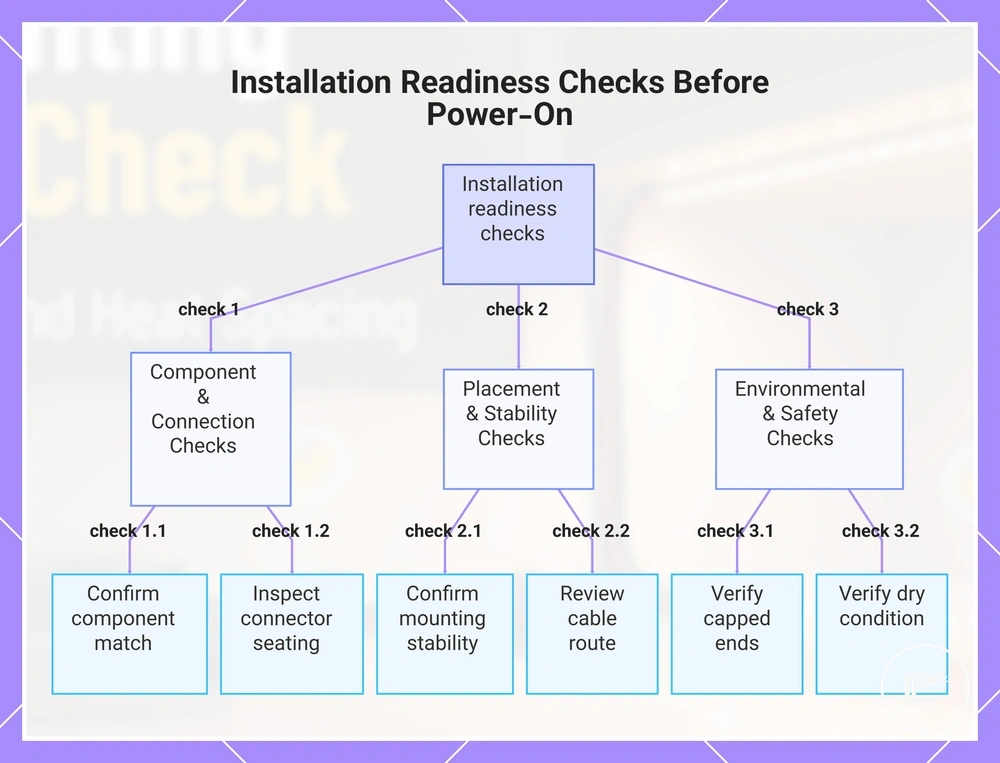
Installation readiness checks before power-on
Installation readiness checks before power-on confirm that the lighting setup is ready for a controlled first test only after compatibility, heat, wiring, and mounting conditions have been verified. Readiness depends on component match, secure connections, stable placement, and the absence of exposed, loose, wet, or unstable conditions that should be corrected before power-on.
Installation readiness checks before power-on organize final pre-power verification in a safe order.
- Confirm component match before connection.
- Review the mock layout and verify that all parts fit the intended installation.
- Check that strip cut points follow the intended connection plan.
- Verify that capped ends are present where exposed strip ends require protection.
- Inspect connector seating and confirm that connections remain secure.
- Review the cable route for strain, movement, or potential contact issues.
- Confirm mounting stability and correct any loose or sagging placement.
- Verify that the installation is in a dry condition before power-on.
- Ensure that a switch-off point remains accessible during the first test.
A lighting setup that passes these readiness criteria may reduce the likelihood of issues from mismatched, exposed, loose, wet, or unstable conditions. If any verification item remains unresolved, pause the pre-power check and correct the condition before proceeding. This keeps the first power-on controlled rather than treated as a troubleshooting step.
Suitable safety accessories can support this checklist after the readiness criteria are understood and verified. Accessories should be treated as support measures rather than replacements for final verification.
Here are product examples that may make comparison easier. Before buying, always review the compatibility criteria, essential features, and product details.
This chart shows the key verification checks to perform before powering on a lighting installation, organized by component, placement, and environmental conditions.
Component compatibility and mock layout checks
Component compatibility and mock layout checks confirm that the strip, power supply, dimmer, connectors, channels, and cable paths fit safely before permanent mounting. The mock layout should verify voltage family, connector type, channel fit, cable reach, bend path, and switch position before the strip is cut, stuck, or powered. A 12V setup should stay within the 12V voltage family, and a 24V setup should stay within the 24V voltage family.
Component compatibility and mock layout checks can be reviewed through these local fit points:
- Compare the strip label with the power supply output and connected controller or dimmer rating.
- Check that each connector type matches the strip contacts and intended connection path.
- Test channel fit before mounting so the strip, diffuser, and cable exit path sit without pressure.
- Confirm that cable reach is sufficient without pulling, sharp bending, or strain at the connector.
- Review bend radius around corners so the strip and cable path do not force an unsafe fit.
- Place the switch position where switch-off remains accessible during the first controlled test.
- Correct visible mismatches before cutting, sticking, or powering the strip.
Cut ends, capped sections, and unused strip pieces
Cut ends, capped sections, and unused strip pieces remain electrical and physical safety points until they are capped, insulated, or removed from the active setup. Exposed copper pads and exposed contact points should not be left accessible because accidental contact may increase the risk of a short circuit, overheating, or an unsafe condition. Moisture, poor ventilation, or damaged insulation around cut ends can increase risk and should be corrected before power-on.
Cut ends, capped sections, and unused strip pieces can be checked by separating cut-point inspection, capping, and storage risks:
- Check that cut marks are clearly identified and that nearby strip material is not damaged.
- Inspect exposed copper pads and confirm they are not left open to accidental contact.
- Verify that end caps or insulation cover cut ends where protection is needed.
- Keep polarity marks visible enough to avoid uncertain reconnection.
- Store or remove unused strip fragments so loose pieces cannot contact powered parts.
- Review cut ends for signs of heat buildup, damaged insulation, or exposed contact.
- Stop use if cut ends are damaged, wet, uncapped, or positioned where accidental contact may occur.
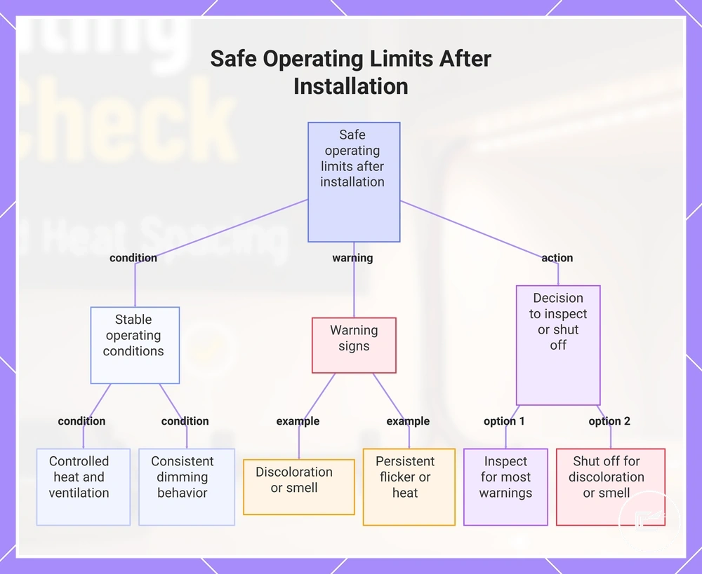
Safe operating limits after installation
Safe operating limits after installation depend on runtime, heat, ventilation, dimmer behavior, and the condition of the installed components. Extended use may be appropriate when heat remains controlled, driver ventilation is unobstructed, and no visible warning signs are present. Operating limits should be reviewed when operating conditions change or visible wear appears.
Safe operating limits after installation can be organized by operating condition and warning sign.
- LED strip runtime and continuous use: continue use when operating conditions remain stable; inspect if heat increases or performance changes.
- Temperature feel and heat: inspect the installation if surfaces become unusually warm or heat buildup appears inside an enclosure.
- Driver ventilation: continue use when ventilation openings remain unobstructed; inspect if airflow becomes restricted.
- Dimmer behavior: inspect if dimming becomes inconsistent or causes unexpected flicker.
- Cabinet enclosure: review operating conditions when enclosed spaces may reduce ventilation around the lighting system.
- Discoloration or smell: shut off power and inspect if discoloration, unusual odor, or visible material changes appear.
- Flicker: inspect connections and operating conditions if flicker develops after normal operation.
- Cord movement: inspect and secure cable routing if cords shift, loosen, or move into contact-risk areas.
Visible warning signs should trigger an inspection or shutoff decision rather than continued use. Discoloration, unusual smell, persistent flicker, restricted ventilation, or unexpected heat may indicate conditions that require attention. Switch access should remain available so power can be disconnected quickly when a warning sign appears. Continued use depends on operating condition, load, ventilation, and component condition.
Accessory choices can support safe operating limits when they match the installation requirements and operating conditions. For broader upkeep guidance after installation, see long-term maintenance.
Here are product examples that may make comparison easier. Before buying, always review the compatibility criteria, essential features, and product details.
This chart shows the conditions that allow continued safe operation and the warning signs that require inspection or shutoff after LED strip installation.
Leaving LED strips on overnight or continuously
Leaving LED strips on overnight or continuously is safer only when the system is correctly rated, ventilated, protected, and free of heat or wiring issues. Extended operation can increase risk when the power supply is overloaded, strip heat builds up, ventilation is blocked, moisture is present, or damaged parts remain in use. Low-brightness cabinet lighting in an open, cool, supported setup may be lower risk than a covered, warm, enclosed, or damaged installation.
Leaving LED strips on overnight or continuously should depend on these extended-use conditions:
- Confirm that the power supply capacity is suitable for the connected strip load.
- Check strip heat during operation and inspect if heat buildup becomes noticeable.
- Use channel support where it helps keep the strip stable and exposed to airflow.
- Review enclosed spaces because limited ventilation may increase overheating risk.
- Check the dimmer setting and reduce extended use if unstable dimming or flicker appears.
- Keep moisture away from drivers, connectors, exposed contact points, and strip ends.
- Use supervision or periodic checks when conditions are new, enclosed, warm, or uncertain.
- Keep switch accessibility clear so the lighting can be turned off quickly.
- Stop use if overheating, a burning smell, exposed contact, moisture, or damaged wiring appears.
Early signs of overheating, discoloration, or wear
When unusual warmth, discoloration, flicker, or buzzing develops, the symptom may indicate a condition that needs inspection before continued use. Early warning signs can appear as heat, electrical, or material changes rather than complete failure. A warning sign does not identify a single cause, but it can help determine whether inspection or shutoff is the safer next action.
Early signs of overheating, discoloration, or wear separate heat, electrical, and material warning signs that should not be ignored:
- Unusual warmth: inspect the installation if abnormal heat develops during normal operation.
- Hot driver: check operating conditions if the driver becomes unusually hot during use.
- Discoloration: inspect the installation if strip surfaces, channels, wires, or nearby materials change color.
- Melting adhesive: inspect mounting stability and stop use if adhesive appears melted or distorted.
- Buzzing: inspect power and connection conditions if buzzing develops unexpectedly.
- Burning smell: shutoff power and stop use immediately.
- Flicker: inspect connections and operating conditions if flicker becomes persistent.
- Intermittent connection: inspect connectors, contact points, and cable routing if operation becomes inconsistent.
- Brittle insulation: inspect wiring if insulation becomes cracked, hardened, or damaged.
- Loose mounting: inspect support points if strips, channels, or cables begin to detach or move.
Burning smell, melted parts, exposed conductors, repeated power failures, or abnormal heat are stop-use symptoms that require immediate shutoff before continued operation. For symptom escalation beyond these early warning signs, see troubleshooting unsafe symptoms.
Conditions that should stop installation
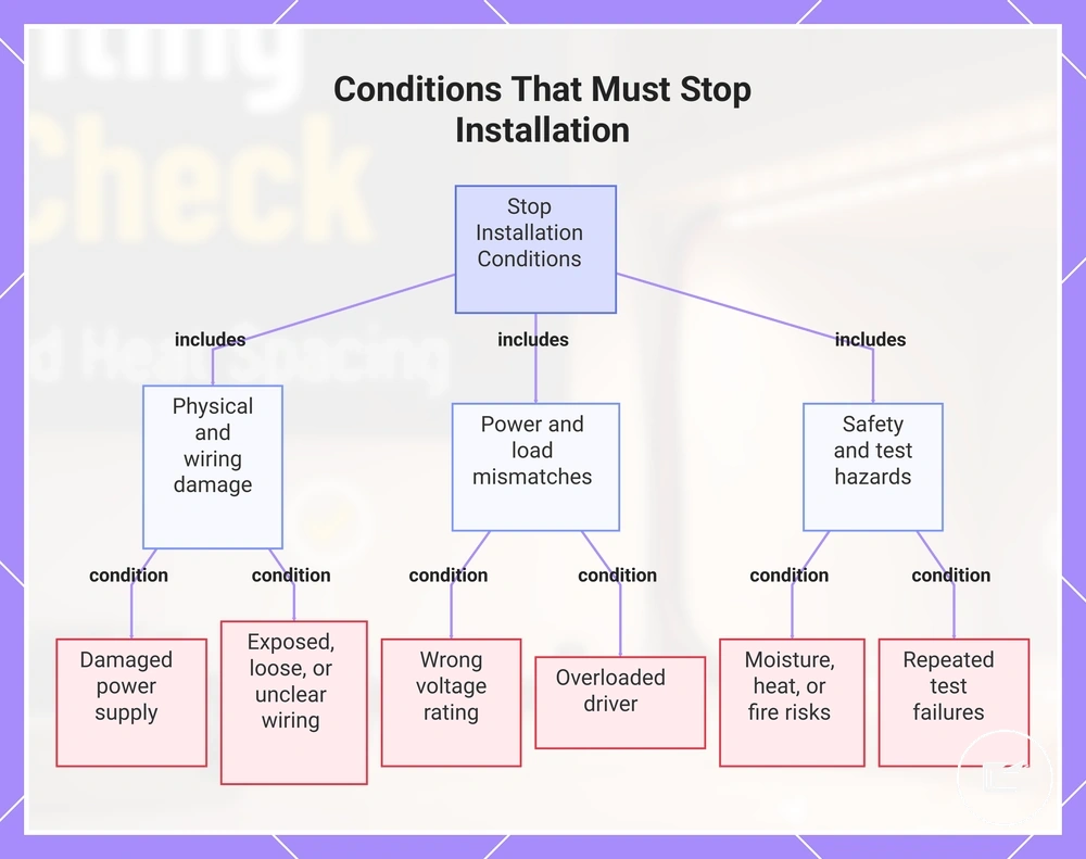
An unsafe condition should stop installation when there is a clear risk of overheating, short circuit, exposed contact, fire hazard, or uncertain electrical safety. Installation should not continue when damage, wrong voltage, moisture exposure, blocked ventilation, or unresolved safety concerns are present. Stopping early is safer than continuing with components that may create an unsafe condition during testing or operation.
Conditions that should stop installation include visible damage, power mismatches, heat concerns, and unresolved wiring questions. These conditions may affect electrical safety, component protection, or system reliability. If a condition cannot be verified confidently, installation should be paused until it is clarified.
Conditions that should stop installation separate component, wiring, power, heat, moisture, and uncertainty triggers that require immediate action:
- Damaged power supply: stop use if the housing, cable, plug, or connector is damaged.
- Wrong voltage: do not continue if component voltage ratings do not match.
- Overloaded driver: stop installation if the driver may be operating beyond its intended load.
- Exposed copper: stop use if conductors or exposed contact points are accessible.
- Loose connectors: do not continue with unstable or poorly seated connections.
- Moisture exposure: stop installation if moisture is present near power, wiring, or connection points.
- Hot components: stop use if abnormal heat or overheating develops during testing.
- Flammable contact: do not continue if lighting or wiring touches materials that may increase fire hazard risk.
- Unclear hardwiring: stop installation if wiring identification, routing, or connection status is uncertain.
- Repeated test failures: pause installation if the same fault appears repeatedly after rechecking the setup.
Professional electrical help is appropriate when mains wiring is involved, hidden wiring cannot be verified, overheating repeats, or component ratings remain unclear after inspection. These conditions require escalation rather than continued installation.
This chart groups the specific conditions that require immediate installation stoppage into three main categories: physical and wiring damage, power and load mismatches, and safety and test hazards.