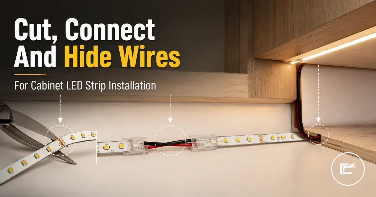
LED Strip Wire Installation for Cabinets
LED strip wire installation for cabinets is the work of routing, joining, and supporting LED strip wires so cabinet lighting can follow the cabinet shape. The scope includes cut points, copper pads, connectors, extension wire, corner turns, wire cover placement, cable clips, and polarity checks inside a cabinet-specific wiring path.
When a strip light crosses a cabinet gap, turns around an inside edge, or needs to reach a power-entry position, the wire route affects visibility, access, and connection stability. A connector clip may close on the strip, but correct contact still depends on strip type, pin count, copper pad alignment, and polarity. This page stays focused on low-voltage strip wiring rather than broad power-system sizing or a full under-cabinet mounting process. For the wider category context, see home LED strip and cabinet lighting accessories.
The main problem is that a clean cabinet finish can hide weak connections if wires are pressed, bent, or trapped without inspection access. A safer plan keeps each connector, extension wire, corner connector, wire cover, and cable clips reachable enough for later checks when the cabinet layout allows it. The next step is to understand where the cut points and connection basics begin.
What Changes When LED Strips Are Cut and Reconnected
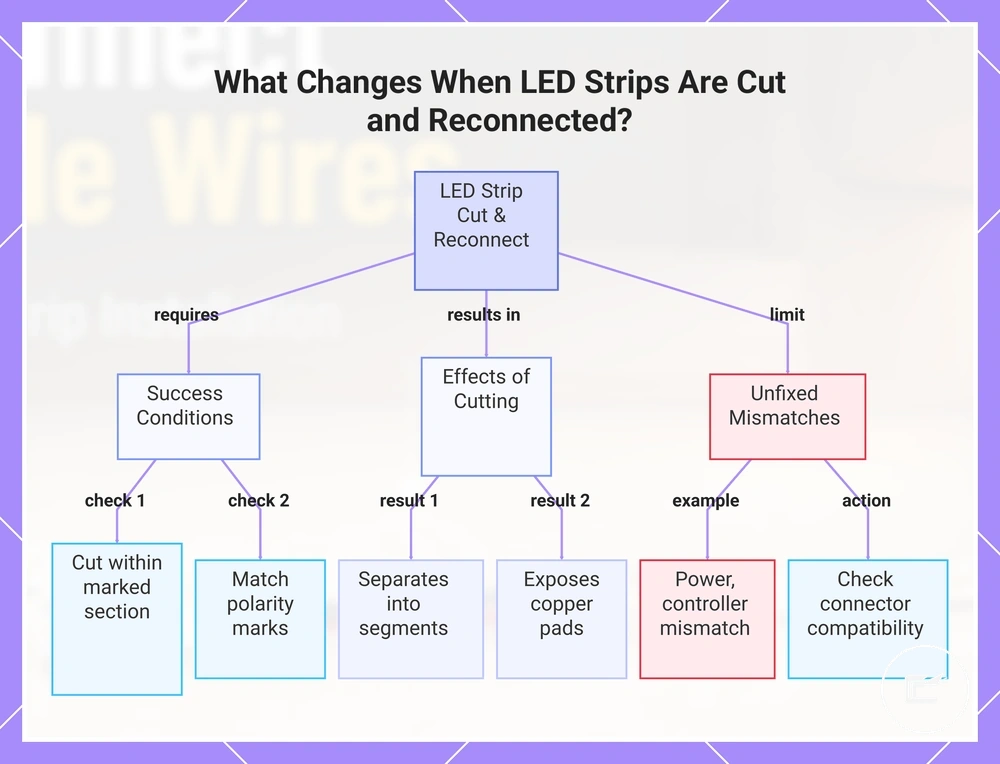
A cut and reconnected LED strip may still work when the cut line, copper pads, polarity, and connector contact are correct. Cutting should stay within a marked cuttable section, not an unmarked part of the LED tape.
A cut separates the LED strip into segments and exposes the copper pads that allow reconnection. The polarity marks, such as plus mark and minus mark, still need to match the connector or wire path so circuit continuity can continue through the rejoined strip. Adhesive backing and strip coating can also affect how easily the pads sit inside a connector, because poor pad exposure may weaken connector contact.
Cutting changes the usable end, the routing options, and the connection point, but it does not by itself correct a power supply, controller, or strip-type mismatch. For those limits, check connector and power compatibility before treating a reconnected strip as ready for cabinet installation.
This chart shows the conditions for successful reconnection, the effects of cutting, and the limitations that require separate checks.
What Changes When LED Strips Are Cut and Reconnected
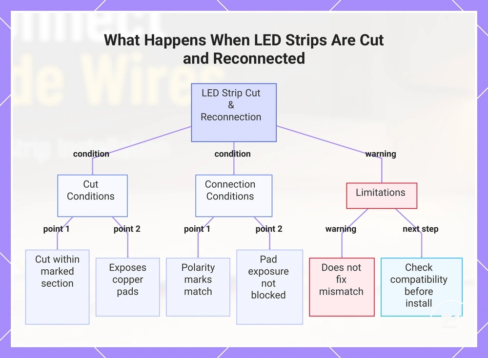
A cut and reconnected LED strip may still work when the cut line, copper pads, polarity, and connector contact are correct. Cutting should stay within a marked cuttable section, not an unmarked part of the LED tape.
A cut separates the LED strip into segments and exposes the copper pads that allow reconnection. The polarity marks, such as plus mark and minus mark, still need to match the connector or wire path so circuit continuity can continue through the rejoined strip. Adhesive backing and strip coating can also affect how easily the pads sit inside a connector, because poor pad exposure may weaken connector contact.
Cutting changes the usable end, the routing options, and the connection point, but it does not by itself correct a power supply, controller, or strip-type mismatch. For those limits, check connector and power compatibility before treating a reconnected strip as ready for cabinet installation.
This chart shows the key conditions for successful LED strip reconnection after cutting, along with the limitations and required checks.
Cutting LED Strip Sections at the Correct Copper Pads
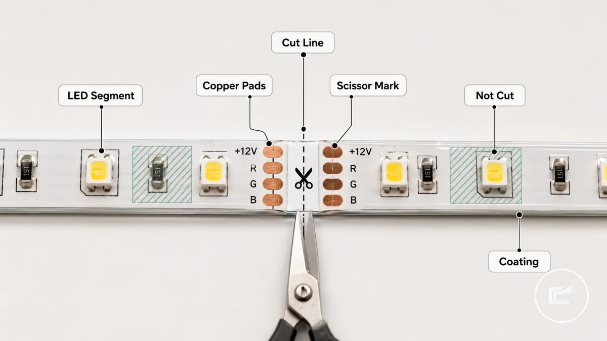
Cutting LED strip sections starts at the marked cut line, not through an LED segment or an unmarked area. The usable cutting point is the scissor mark beside the marked copper pads.
Copper pads are the exposed contact areas that allow later connector contact or solder pad use when the strip type supports reconnection. A marked section may show a scissor mark, dotted cut line, or paired pads across the LED tape. Strip coating can hide or stiffen the pad area, so pad exposure may need careful checking before a connector can grip it.
Cutting LED Strip Sections at the Correct Copper Pads depends on seeing the cut line, copper pads, scissors direction, and not-cut zones before any cut is made. The image labels the safe cut area, and the steps should be used only after the strip is disconnected from power.
- Find the scissor mark or cut line on the marked section, and avoid cutting through the LED segment because that can damage the usable circuit path.
- Check that the copper pads are visible on both sides of the cut line, and avoid a point where coating blocks pad exposure.
- Align sharp scissors or a suitable cutting tool across the cut line, and keep the blade square to reduce the risk of a slanted or damaged pad edge.
- Make one straight cut through the marked copper pad area, and avoid twisting the strip because a bent end may weaken later connector contact.
- Inspect the clean edge after cutting, and do not treat a damaged pad or unmarked cut as reliably reconnectable without checking the strip type and contact surface.
Reconnecting Cut LED Strips with Solderless Connectors or Soldering
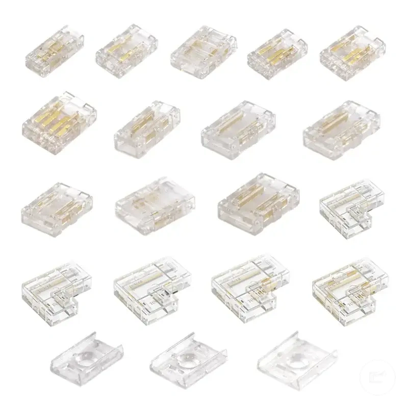
Reconnecting cut LED strips depends on access, removability, and the condition of the cut ends. A solderless connector may suit accessible joins that may need to be reopened, while soldering may suit fixed joins when access and skill allow. Both methods require correct copper pad alignment, making solderless connectors and soldering conditional methods.
A solderless connector uses a connector clip to hold the strip section against the copper pads. Strip-to-strip connector designs join two cut ends directly, while a strip-to-wire connector connects the strip to cable leads. Correct copper pad contact and matching polarity are required before closing the connector clip. Misaligned pads or reversed polarity can prevent the connection from functioning as intended.
Reconnecting Cut LED Strips with Solderless Connectors or Soldering is easier to understand when the contact points and alignment differences are visible. The image compares pad alignment, polarity marks, and strain relief considerations for both methods.
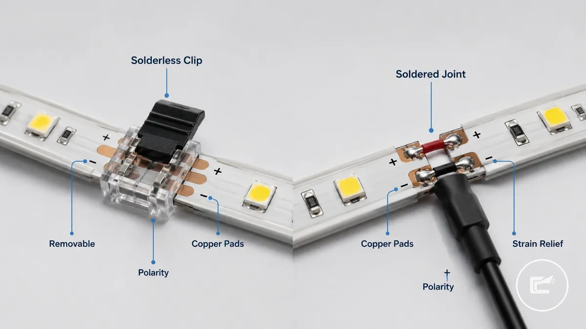
Soldering and solderless connectors involve different trade-offs. A soldered joint may offer greater durability when copper pad contact is clean and strain relief is managed, but it usually requires more skill and working space. A solderless connector can support a removable connection in accessible cabinet areas, though reliability may depend on pad condition, connector fit, movement, and installation quality. Before choosing a method, verify polarity, plus minus alignment, and channel order, then review connector and power compatibility as part of the selection criteria.
Cabinet access, tight corners, vibration risk, and future maintenance needs often influence the choice. A removable connection may suit locations where later access is expected, while a fixed splice may suit areas with limited movement when suitable strain relief is provided.
| Method | Best use case | Main condition | Main risk |
|---|---|---|---|
| Solderless connector | Accessible and removable connection | Accurate copper pad contact and polarity alignment | Contact quality may vary if pad alignment, fit, or movement changes |
| Soldering | Fixed connection when access and skill allow | Clean pad alignment and suitable strain relief | Results may vary with installation quality and working access |
Matching Connectors to Strip Width, Pin Count, and Polarity
Connector fit depends on matching the cut strip to the connector's physical and electrical requirements. Before closing a connector, verify strip width, pin count, and polarity.
A connector can close around a strip and still fail to make correct electrical contact if copper pad alignment or channel order is incorrect. Strip width affects physical fit within the connector channel, while pin count must match the strip channel type, such as 2-pin or 4-pin layouts. Correct polarity, plus mark and minus mark alignment, copper pad alignment, and connector pressure also matter because operation may depend on pad exposure and contact alignment.
Use this local checklist before pressing a cut strip into a connector:
- Confirm the strip width matches the connector channel for proper physical fit.
- Verify the pin count matches the strip channel type, since mismatched pin count can cause incorrect channel contact.
- Check the plus mark and minus mark against the connector polarity markings.
- Confirm the channel order matches the connector contact layout.
- Inspect copper pad alignment and verify connector pressure is applied evenly after the clip latch closes.
- Test the connection before final mounting because pad exposure, alignment, and contact pressure may still affect operation.
Choosing Strip-to-Strip or Strip-to-Wire Connections
When two strip sections meet directly, a direct join is the appropriate connection style. When a cabinet gap separates the strip ends, a wire-gap join becomes the practical choice, making strip-to-strip connectors and strip-to-wire connectors suitable for different conditions.
The decision depends on cabinet separation, bend radius, access, and visible wire exposure. A strip-to-strip connector suits adjacent strip ends, while a strip-to-wire connector suits a separated route that needs a jumper wire between connection points. The distinction is direct contact versus a wire gap between strip sections.
- If two strip ends are adjacent with little or no cabinet gap, use a strip-to-strip connector because the contact points can join directly.
- If cabinet separation creates a wire gap between strip sections, use a strip-to-wire connector because a wired join can bridge the route.
- If a corner creates a tight bend radius, use a strip-to-wire connector because a short jumper wire may follow the turn more easily than a direct join.
- If access is limited behind cabinet panels or trim, a strip-to-wire connector may allow a more practical routing path through the available opening.
- If visible wire is a concern, choose the connection style that allows the wire path to be concealed more effectively along the cabinet edge or clip path.
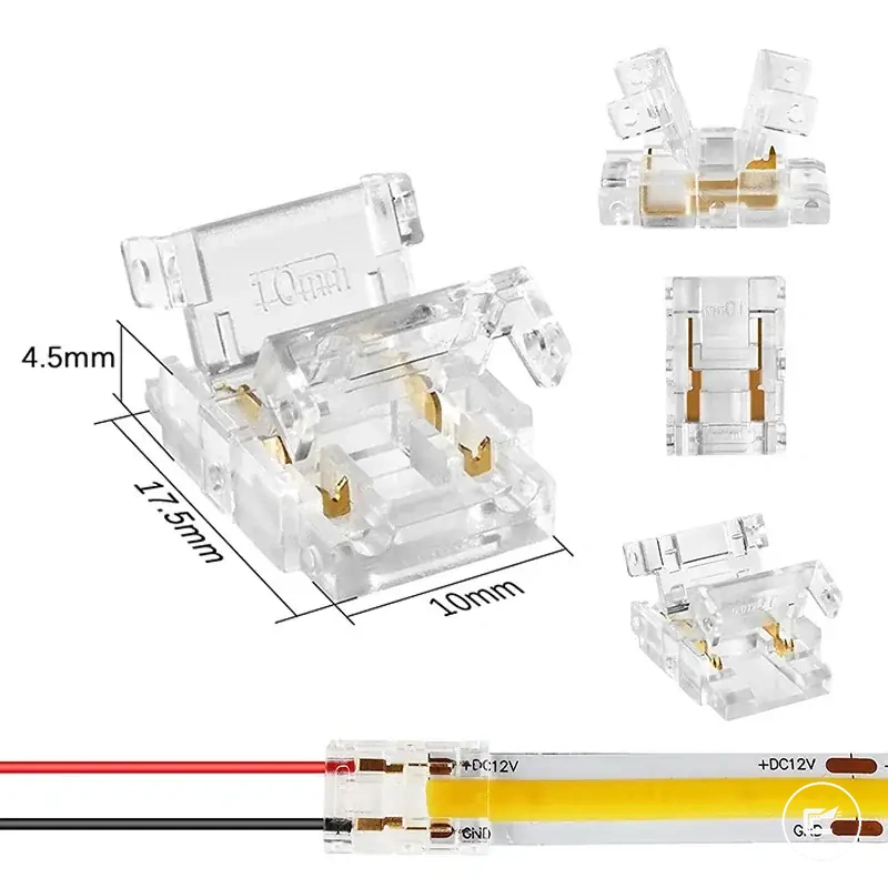
Securing Connector Clips So the Contact Pads Stay Aligned
Keeping a connector clip secure starts with correct pad seating and latch closure. When contact pads shift after mounting, contact quality may be affected, so the goal is consistent pad alignment between the strip and the connector clip.
Contact pressure helps the contact teeth stay aligned with the exposed contact pads. Strip coating, cable strain, and mounting conditions can affect clip fit, so strain relief and adhesive support may help reduce movement after installation. Use the steps below to keep the connection aligned after seating.
- Insert the strip fully into the connector clip until the contact pads reach the intended contact point.
- Check that strip coating does not limit pad exposure where the contact teeth meet the contact pads.
- Close the latch completely and confirm the connector clip remains aligned without shifting.
- Provide strain relief with suitable cable routing and adhesive support to reduce movement at the connection.
- Perform a gentle pull-test to confirm the strip remains seated and the pad alignment does not change during light movement.
As a local warning, insufficient latch pressure, cable movement, or shifting pad alignment may contribute to loose contact symptoms after mounting.
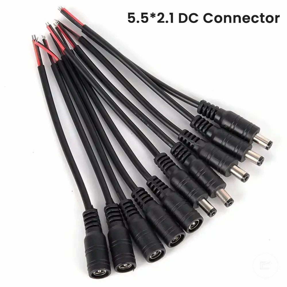
Using Extension Wire Between Cabinet Gaps and Power Locations
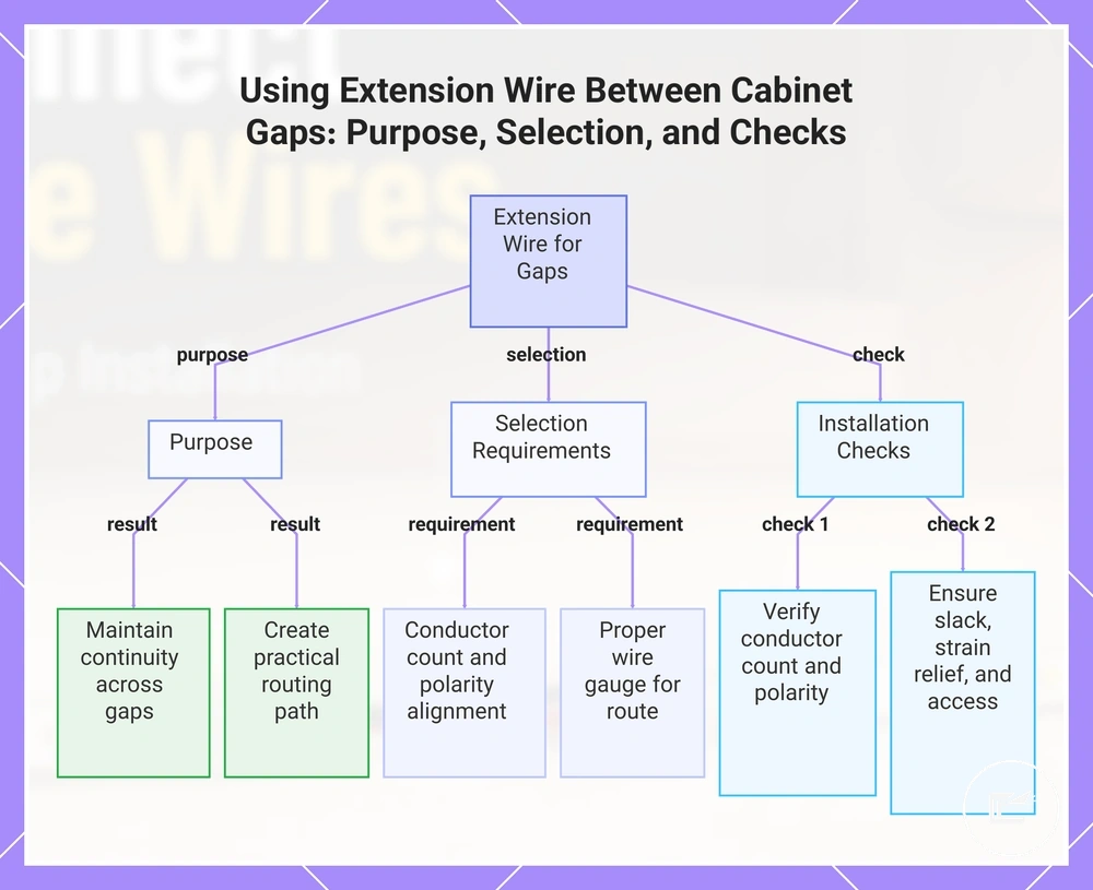
When a cabinet gap separates two LED strip sections or the power location sits away from the lighting run, an extension wire can bridge the distance without forcing the strip around every obstacle. This approach helps maintain continuity across separated cabinet sections and creates a more practical routing path. That is why extension wire is often used between cabinet gaps and remote connection points.
Extension wire selection depends on the route length, conductor count, and access path available inside the cabinet layout. The conductor count should match the strip type so polarity and channel mapping remain aligned through the connection. Wire gauge requirements may vary with strip power, distance, and manufacturer recommendations, so route planning is usually more important than assuming a single wire size fits every installation. Accessible routing also makes later inspection and adjustments easier if the cabinet configuration changes.
A cabinet gap is the condition, extension wire is the attribute, and maintained continuity is the intended effect. When the gap passes near an appliance opening, between separated upper cabinets, or toward a remote adapter position, the wire route should allow access while reducing unnecessary tension on connector ends. Conductor count and polarity should remain matched throughout the run. For related limits on matching components, see connector and power compatibility.
Before finalizing the route, verify these connection and routing conditions:
- Confirm the extension wire matches the required conductor count.
- Check that connector ends align with the intended polarity.
- Choose a wire gauge appropriate for the route length and strip requirements.
- Leave enough slack to avoid tension during cabinet movement or maintenance.
- Add strain relief where movement could pull on the connection.
- Use cable clips or similar support to maintain the concealment path.
- Keep the route accessible for future inspection when practical.
This chart shows the purpose of using extension wire to bridge cabinet gaps, the key selection criteria, and essential installation checks to ensure continuity and practical routing.
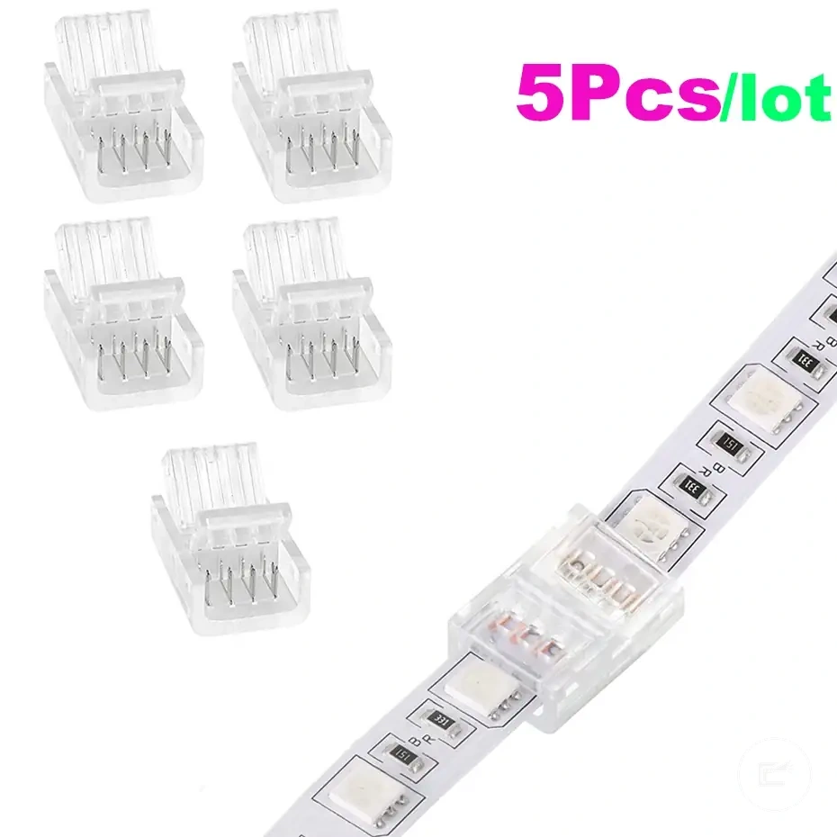
Matching Extension Wire to Single-Color, RGB, RGBW, or CCT Strips
Extension wire must match the strip channel type so each required circuit path continues correctly. The conductor count, polarity, and channel order must match the strip configuration.
A single-color strip uses a two-wire arrangement with a positive lead and a negative return path, while RGB, RGBW, and CCT strips use additional channel lead connections. Connector orientation must keep each channel lead aligned with its intended contact point. Even when conductor count matches, polarity and channel order must also match to maintain correct circuit mapping.
The table below compares common strip types and the wire-matching checks needed before connecting an extension wire.
| Strip type | Required conductors | Match check | Risk if wrong |
|---|---|---|---|
| Single-color strip | 2-wire | Positive lead and polarity alignment | Connection may not operate as intended |
| RGB | 4-pin | Conductor count, polarity, and channel order | Color channels may not map correctly |
| RGBW | 5-pin | Positive lead, white channel, and channel lead mapping | Channel behavior may differ from the intended mapping |
| CCT | Multi-channel strip | Polarity and warm-cool channel orientation | Warm and cool channel response may not follow the intended order |
Using Extension Wire Between Cabinet Gaps and Power Locations
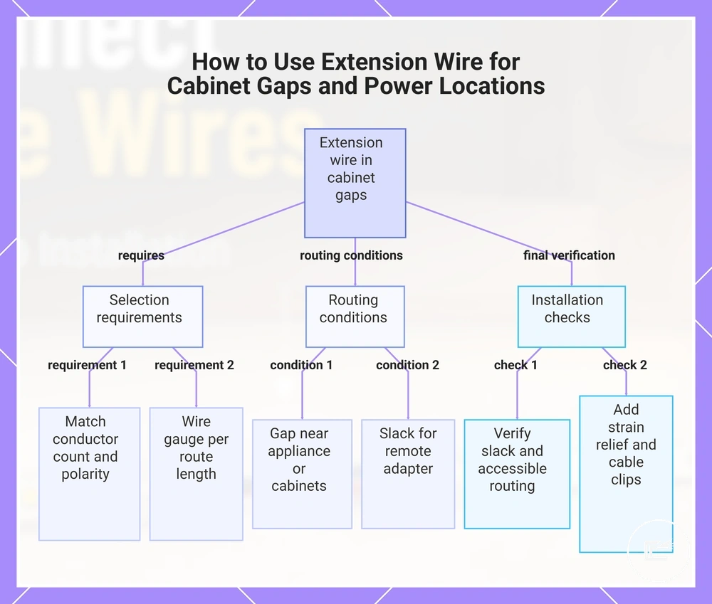
When a cabinet gap separates two LED strip sections or the power location sits away from the lighting run, an extension wire can bridge the distance without forcing the strip around every obstacle. This approach helps maintain continuity across separated cabinet sections and creates a more practical routing path. That is why extension wire is often used between cabinet gaps and remote connection points.
Extension wire selection depends on the route length, conductor count, and access path available inside the cabinet layout. The conductor count should match the strip type so polarity and channel mapping remain aligned through the connection. Wire gauge requirements may vary with strip power, distance, and manufacturer recommendations, so route planning is usually more important than assuming a single wire size fits every installation. Accessible routing also makes later inspection and adjustments easier if the cabinet configuration changes.
A cabinet gap is the condition, extension wire is the attribute, and maintained continuity is the intended effect. When the gap passes near an appliance opening, between separated upper cabinets, or toward a remote adapter position, the wire route should allow access while reducing unnecessary tension on connector ends. Conductor count and polarity should remain matched throughout the run. For related limits on matching components, see connector and power compatibility.
Before finalizing the route, verify these connection and routing conditions:
- Confirm the extension wire matches the required conductor count.
- Check that connector ends align with the intended polarity.
- Choose a wire gauge appropriate for the route length and strip requirements.
- Leave enough slack to avoid tension during cabinet movement or maintenance.
- Add strain relief where movement could pull on the connection.
- Use cable clips or similar support to maintain the concealment path.
- Keep the route accessible for future inspection when practical.
This chart shows the key factors for selecting extension wire, the routing conditions to consider, and the final verification steps for a successful installation.
Using Corner Connectors for Inside Edges and Angle Changes
When a cabinet inside edge creates an angle change that would stress or lift the LED strip, a corner connector can keep the strip flatter through the turn. A corner connector is useful when bending the strip would make the route unreliable or visually uneven.
An L-shaped connector or flexible connector must keep copper pad alignment and polarity correct through the corner. Corner spacing, adhesive support, and strain relief also affect whether the connection stays seated after mounting. For example, an inside edge under a cabinet may need a short flexible connector so both strip ends remain flat on their mounting surfaces.
Use these local steps when fitting a corner connector through an angle change:
- Align the strip ends with the corner connector so the copper pads meet the correct contact points.
- Check polarity before insertion so the positive and negative paths continue through the angle change.
- Insert each strip end into the L-shaped connector or flexible connector without forcing the pads past the contact area.
- Secure the wire route with adhesive support and strain relief so corner movement does not pull on the connection.
Hiding LED Strip Wires Under and Inside Cabinets
When LED strip wiring remains visible along cabinet surfaces, the installation can appear unfinished and the wire route may be more exposed to accidental movement. To hide LED strip wires effectively, the route should follow cabinet features such as an underside edge, cabinet back, or shelf gap while preserving inspection access.
Hiding LED Strip Wires Under and Inside Cabinets works best when wiring stays concealed from normal sightlines without trapping future access points. The image shows wire management methods that maintain a clean finish while keeping connections serviceable.
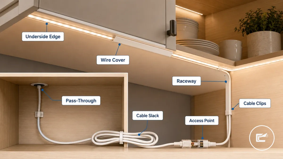
An underside edge can conceal wires from view, while a cabinet back may provide a longer protected route. A wire cover, raceway, or surface channel can help organize cable management along exposed surfaces. Suitable pass-through locations depend on cabinet material, route accessibility, and the need to maintain cable slack and future inspection access.
Hidden from view is not the same as inaccessible. Cable clips, cable slack, and reachable connection points help preserve serviceability, while concealed routes that trap wiring can make inspection access more difficult. Before covering connection points, review safe wiring checks to confirm that concealed wiring remains inspectable and serviceable.
Use this routing checklist to organize concealment options while maintaining access:
- Route wires along an underside edge when the cabinet profile can conceal the path from normal sightlines.
- Use the cabinet back when a longer concealed route is needed and inspection access remains available.
- Use a wire cover or raceway where surface-mounted wiring would otherwise remain visible.
- Secure the route with cable clips to reduce movement and help maintain strain control.
- Leave cable slack near accessible connection points to support future inspection or adjustment.
- Use a suitable pass-through that allows routing while preserving access to the wire path.
Routing Wires Through Cabinet Backs, Edges, and Gaps
Routing wires through cabinet spaces starts with choosing a hidden route that remains accessible for future checks and adjustments. Cabinet backs, side edges, shelf gaps, and adjoining cabinet spaces can provide practical paths when cable slack and access are preserved, making the cabinet back, side edge, shelf gap, and adjoining cabinet the primary routing surfaces.
Each route changes visibility, access, and strain differently. A hidden route should remain a reachable route, and cable slack should be maintained near connection points to reduce tension during inspection or repositioning. Avoid relying on structural drilling because pass-through suitability depends on cabinet construction and conditions that may require professional judgment.
Use these route options to balance concealment, access, and strain control:
- Cabinet back: Provides a hidden route along the rear surface; helps reduce visibility; keep a reachable route for future inspection.
- Rear corner: Uses the cabinet back and corner transition to conceal wiring; can keep the path out of normal sightlines; maintain cable slack to reduce strain at the turn.
- Side edge: Follows an inside vertical edge route; can support access from the cabinet side; avoid tight routing that may increase cable strain.
- Shelf gap: Uses a shelf gap as a pass-through between spaces; can simplify access across cabinet sections; suitability depends on available clearance and cabinet construction.
- Adjoining cabinet: Extends the route through an adjoining cabinet space; can keep wiring concealed while remaining reachable; ensure inspection access remains available after installation.
- Appliance gap: Uses an appliance gap where visibility is reduced; can support a hidden route when access remains possible; avoid trapping wiring where inspection becomes difficult.
Using Raceways, Wire Covers, and Cable Clips for a Clean Finish
Organizing visible LED strip wiring starts with selecting an accessory that matches the surface route and access needs. Raceways, wire covers, and cable clips help manage wiring after the connection path is chosen, supporting a cleaner surface route while maintaining access through raceways, wire covers, and cable clips.
Removability, surface fit, and strain control should guide the choice. Adhesive clips may suit a cabinet underside when the surface condition supports attachment, while screw clips may be suitable where the mounting surface allows them. A wire cover or low-profile channel can help maintain service access in a removable-management setup, and cable slack should remain available to support strain control and future adjustments.
The accessories serve different wire-management roles. Use the comparison below to match the accessory type to the intended surface route and access requirement.
| Accessory | Best use | Caution |
|---|---|---|
| Raceway | Managing a surface route with a low-profile channel for a cleaner finish | Service access should remain available after installation |
| Wire cover | Reducing wire visibility along exposed cabinet surfaces | Clean appearance may depend on cabinet material, surface condition, and color matching |
| Cable clips | Holding wiring in position and supporting strain control | Adhesive clips may vary in hold depending on surface texture, cabinet finish, and cable weight |
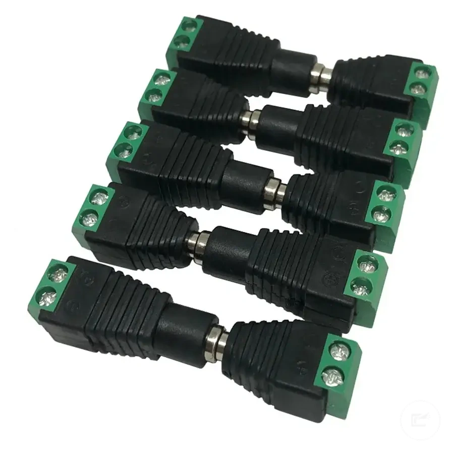
Using Extension Wire Between Cabinet Gaps and Power Locations
When a cabinet gap separates two LED strip sections or the power location sits away from the lighting run, an extension wire can bridge the distance without forcing the strip around every obstacle. This approach helps maintain continuity across separated cabinet sections and creates a more practical routing path. That is why extension wire is often used between cabinet gaps and remote connection points.
Extension wire selection depends on the route length, conductor count, and access path available inside the cabinet layout. The conductor count should match the strip type so polarity and channel mapping remain aligned through the connection. Wire gauge requirements may vary with strip power, distance, and manufacturer recommendations, so route planning is usually more important than assuming a single wire size fits every installation. Accessible routing also makes later inspection and adjustments easier if the cabinet configuration changes.
A cabinet gap is the condition, extension wire is the attribute, and maintained continuity is the intended effect. When the gap passes near an appliance opening, between separated upper cabinets, or toward a remote adapter position, the wire route should allow access while reducing unnecessary tension on connector ends. Conductor count and polarity should remain matched throughout the run. For related limits on matching components, see connector and power compatibility.
Before finalizing the route, verify these connection and routing conditions:
Here are product examples that may make comparison easier. Before buying, always review the compatibility criteria, essential features, and product details.
- Confirm the extension wire matches the required conductor count.
- Check that connector ends align with the intended polarity.
- Choose a wire gauge appropriate for the route length and strip requirements.
- Leave enough slack to avoid tension during cabinet movement or maintenance.
- Add strain relief where movement could pull on the connection.
- Use cable clips or similar support to maintain the concealment path.
- Keep the route accessible for future inspection when practical.
This chart shows the key selection factors, connection checks, and routing practices for using extension wire to bridge gaps between cabinet sections.
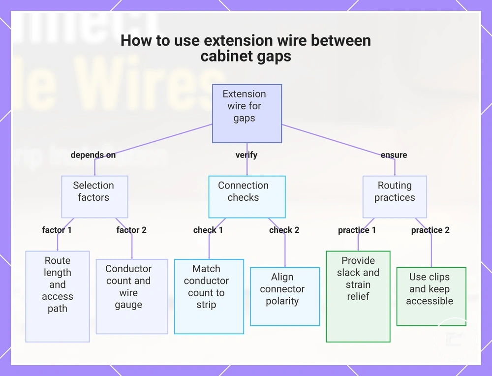
Using Extension Wire Between Cabinet Gaps and Power Locations
When a cabinet gap separates two LED strip sections or the power location sits away from the lighting run, an extension wire can bridge the distance without forcing the strip around every obstacle. This approach helps maintain continuity across separated cabinet sections and creates a more practical routing path. That is why extension wire is often used between cabinet gaps and remote connection points.
Extension wire selection depends on the route length, conductor count, and access path available inside the cabinet layout. The conductor count should match the strip type so polarity and channel mapping remain aligned through the connection. Wire gauge requirements may vary with strip power, distance, and manufacturer recommendations, so route planning is usually more important than assuming a single wire size fits every installation. Accessible routing also makes later inspection and adjustments easier if the cabinet configuration changes.
A cabinet gap is the condition, extension wire is the attribute, and maintained continuity is the intended effect. When the gap passes near an appliance opening, between separated upper cabinets, or toward a remote adapter position, the wire route should allow access while reducing unnecessary tension on connector ends. Conductor count and polarity should remain matched throughout the run. For related limits on matching components, see connector and power compatibility.
Before finalizing the route, verify these connection and routing conditions:
- Confirm the extension wire matches the required conductor count.
- Check that connector ends align with the intended polarity.
- Choose a wire gauge appropriate for the route length and strip requirements.
- Leave enough slack to avoid tension during cabinet movement or maintenance.
- Add strain relief where movement could pull on the connection.
- Use cable clips or similar support to maintain the concealment path.
- Keep the route accessible for future inspection when practical.
Here are product examples that may make comparison easier. Before buying, always review the compatibility criteria, essential features, and product details.