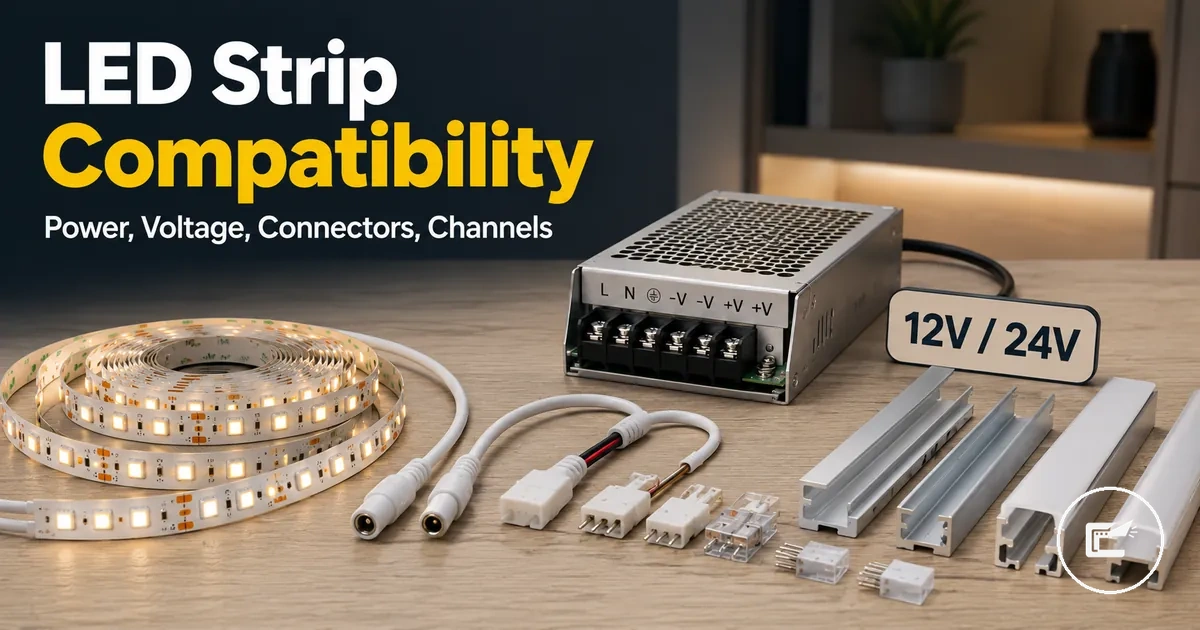
LED Strip Lighting Compatibility for Power, Connectors, Controllers, and Channels
LED strip lighting compatibility depends on matching the strip’s specifications with the power supply, connectors, controllers, and channels that support it. Appearance alone cannot confirm fit because voltage, wattage, strip width, pin count, controller signal, and channel size each control a different part of component matching.
Compatibility planning starts with the LED strip label and then moves outward to the parts that carry power, signal, and physical support. This page treats home LED strip and cabinet lighting accessories as a connected system, where each accessory should reinforce the same strip type and installation context.
A power supply should match the strip voltage and have suitable capacity for the intended length and load. Connectors should match strip width, pin count, copper pad layout, and polarity, while controllers should support the strip’s color type, control signal, and rating. Channels should fit the strip and diffuser with enough space for placement and heat movement, depending on the cabinet layout.
The safest way to evaluate LED strip accessories is to check each component against the strip specifications before treating the setup as compatible. A part may look suitable but still fail the matching criteria if the label, connector layout, controller output, or channel dimensions do not support the specific LED strip configuration.
LED Strip Specifications That Control Compatibility
LED strip specifications are the technical labels that determine whether related accessories can match the strip correctly. These labels define electrical, signal, and physical requirements that influence compatibility decisions. Before comparing accessories, the most important compatibility variable is the LED strip specification itself.
As established in the compatibility overview, accessory matching starts with the strip rather than the accessory. Voltage, wattage per metre, strip width, pin count, color type, and channel fit each affect a different compatibility condition, so a mismatch in one specification may limit otherwise suitable component combinations.
LED Strip Specifications That Control Compatibility are easier to evaluate when the key labels are identified visually. The image below highlights the specifications that influence accessory matching, including voltage labels, wattage labels, strip width indicators, pin pads, controller-related signals, and channel fit considerations.
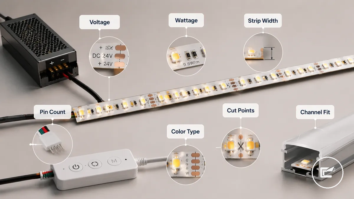
LED Strip Specifications That Control Compatibility can be organized as a specification-to-decision map. Each label below affects a specific matching requirement rather than serving as a standalone product description.
Accessory roles are explained only to the extent needed for compatibility decisions. Broader component definitions are covered in accessory parts explained.
- Voltage: Determines whether a power supply and controller can support the strip's electrical requirements.
- Wattage per metre: Influences power supply sizing and may affect the suitability of longer strip runs.
- Strip width: Limits connector fit and may affect channel selection when space is restricted.
- Pin count: Sets connector and controller matching requirements based on the strip's signal layout.
- Color type: May require a compatible controller signal and matching control method.
- Cut points: Can affect how connectors are used when strip segments are separated or rejoined.
- Channel fit: Depends on strip dimensions, diffuser space, and the available channel profile.
Voltage, Wattage, and Power Supply Matching
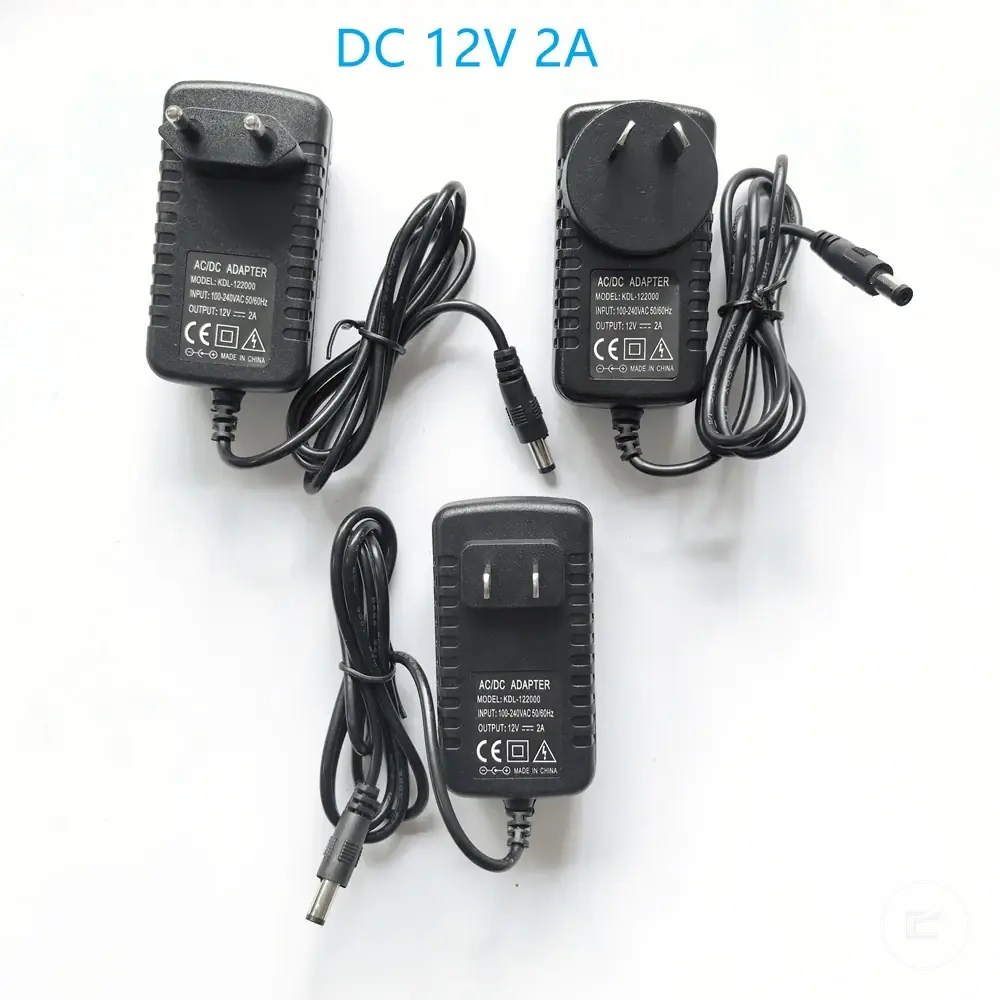
LED strip and power supply compatibility depends on matching voltage first and then verifying that the power supply can support the expected load. The driver output voltage must match the strip voltage, while wattage determines whether the power supply can support the strip length and usage requirements. The key compatibility variable in this section is power supply sizing.
As established by the strip specifications, watts per metre and total strip length work together to determine total load. A longer strip may require more driver capacity, and two strips with the same length can create different load requirements when their wattage per metre differs.
Voltage mismatch creates an incompatibility risk because the strip and driver output are intended to operate within the same voltage category. After voltage is confirmed, total load becomes the next check. The power supply should be able to support the calculated load while maintaining a load margin that suits the application.
For example, two LED strips may have the same length but different watts per metre ratings. The strip with the higher wattage per metre can require greater driver wattage, even though the installed length is the same. This is why total load should be based on strip specifications rather than length alone.
Voltage, wattage, and power supply matching can be organized through the following compatibility checks. The table shows how each input contributes to power matching and where conditional outcomes may influence heat risk or reliability.
| Input | What to check | Why it matters | Safe wording |
|---|---|---|---|
| Voltage | Strip voltage and driver output | Determines basic compatibility | Must match |
| Watts per metre | Power use per unit length | Influences total load calculation | Varies by strip type |
| Total strip length | Installed length | Affects overall power demand | Depends on configuration |
| Total load | Combined power requirement | Guides power supply sizing | Should be calculated from strip data |
| Driver wattage | Available output capacity | Supports expected load | Should suit calculated demand |
| Headroom | Remaining capacity after load | May help reduce overload and heat concerns | Depends on load conditions |
When a power supply operates close to its capacity, heat and reliability outcomes may vary by load, environment, and component design. Broader compatibility precautions are covered in power and heat safety.
This section focuses on matching voltage and capacity requirements. Comparisons between different power source formats are discussed separately in power method comparison.
12V and 24V LED Strip Matching
12V and 24V LED strip matching depends on maintaining the same voltage across the LED strip, power supply, and compatible controls. A 12V LED strip requires a 12V-compatible power setup, while a 24V LED strip requires a 24V-compatible power setup. The key compatibility variable in this comparison is voltage match.
As discussed in the parent power-matching section, voltage labels should be checked before considering run length or accessory compatibility. Run length and voltage drop behavior may differ between a 12V LED strip and a 24V LED strip, so matching decisions should follow the strip voltage and driver output labels rather than assumptions about performance.
12V and 24V LED strip matching can be organized through the following comparison. The comparison highlights match requirements, run-length tendencies, and voltage-drop considerations within the same low-voltage strip category.
| 12V LED Strip | 24V LED Strip |
|---|---|
| Requires a 12V driver output and matching accessory labels | Requires a 24V driver output and matching accessory labels |
| May be more sensitive to voltage drop as run length increases | May be less sensitive to voltage drop under similar run length conditions |
| Check that the strip, power supply, and controller share the same voltage label | Check that the strip, power supply, and controller share the same voltage label |
A 24V LED strip is not universally better than a 12V LED strip, and a 12V LED strip is not automatically the preferred option for every setup. The appropriate choice depends on voltage match, driver output compatibility, run length conditions, and accessory labeling.
Wattage per Metre and Power Supply Headroom
Wattage per metre converts strip length into a minimum power requirement by linking the strip's power use to the total installed length. The calculation is direct: wattage per metre multiplied by strip length produces total wattage. The key compatibility variable in this section is power supply headroom.
Wattage per Metre and Power Supply Headroom can be organized through a simple sizing calculation. The formula and example below show how watts per metre becomes a driver rating input without implying a universal spare-capacity rule.
| Strip length | Watts per metre | Estimated load | Driver size cue |
|---|---|---|---|
| Length value | W/m value | Strip length × W/m | Driver rating should support the calculated load |
| Illustrative example: 5 m | Illustrative example: 10 W/m | 50 W total wattage | Driver capacity may include spare capacity based on product guidance and installation conditions |
The formula can be expressed as total wattage = wattage per metre × strip length. In the illustrative example above, a 5-metre strip rated at 10 watts per metre results in a 50-watt load. Actual values depend on the strip label, selected length, and intended configuration.
After total wattage is calculated, the driver rating can be compared with the expected load. Additional power supply headroom may support reliability and may help limit heat-related stress under certain conditions, but suitable spare capacity varies by driver design, environment, and operating conditions rather than a fixed percentage.
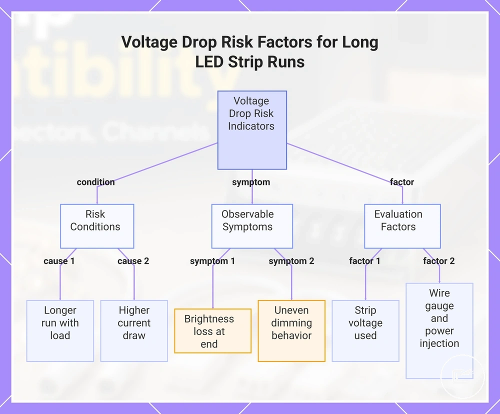
Voltage Drop and Run Length Limits
Longer LED strip runs can increase voltage drop risk even when voltage and wattage appear correct on the product labels. As run length increases, current draw across the strip and connected conductors may influence performance in ways that are not immediately visible during compatibility checks. The key compatibility variable in this section is voltage drop.
Voltage Drop and Run Length Limits can be reviewed through visible performance signals rather than installation changes. The checklist below organizes common conditions and observations that may indicate when run length is affecting compatibility.
- Run length: Longer runs can increase voltage drop risk when distance and load increase together.
- Strip voltage: Voltage-drop effects may vary depending on the strip voltage used in the installation.
- Current draw: Higher current draw may contribute to greater voltage drop under certain strip and layout conditions.
- Brightness loss: Reduced light output toward the end of a run can indicate that voltage is not remaining consistent across the strip.
- Dimming behavior: Uneven dimming behavior may appear when load conditions change across a longer run.
- Wire gauge and power injection: Wire gauge and power injection needs may be factors to evaluate when long-run performance changes are observed.
Voltage drop does not affect every installation in the same way because strip voltage, run length, current draw, wire gauge, and layout conditions can vary. When brightness loss, uneven dimming behavior, or other long-run issues appear, compatibility may need to be reevaluated beyond the original voltage and wattage match. For broader risk considerations when voltage drop becomes a performance concern, see power and heat safety.
This chart shows the risk conditions, observable symptoms, and evaluation factors that indicate voltage drop compatibility issues due to longer LED strip runs.
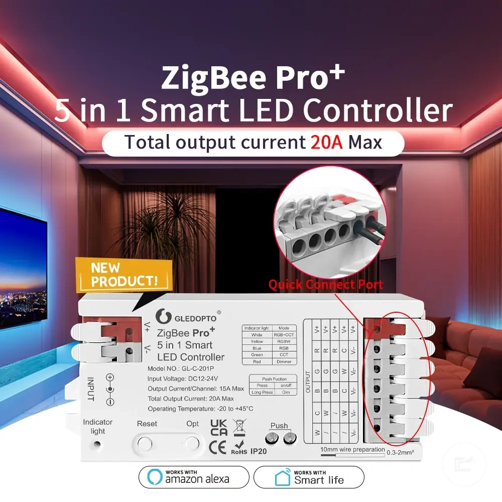
Connector and Extension Cable Compatibility
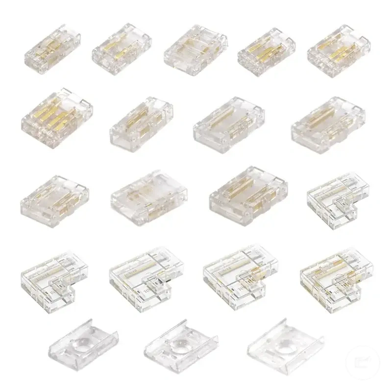
Connector compatibility depends on matching connectors and extension cables to the physical and electrical specifications of the LED strip. Strip width, pin count, copper pads, and polarity must align with the connector or extension cable so the connection can maintain fit and signal continuity. The key compatibility variable in this section is connector compatibility.
Connectors and extension cables should be evaluated against the LED strip specifications already identified earlier in the compatibility process. A connector may appear to fit physically but still fail electrically if pin count, polarity alignment, or copper pad contact does not match the strip configuration.
Connector and Extension Cable Compatibility is easier to assess when the visible fit points are identified before comparing products. The image below labels the attributes that typically determine whether a strip connector or extension lead can align with the LED strip correctly.
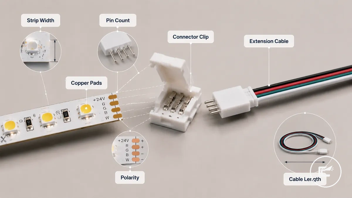
Additional factors such as waterproof coating, connector format, and extension length may influence connection quality. Coated strips can require compatible contact styles, while longer extension cable runs may affect signal continuity or reliability depending on cable design, polarity alignment, and installation conditions.
Connector and Extension Cable Compatibility can be organized through the following comparison of fit and continuity checks. This section focuses on matching attributes rather than connection execution. For cutting, joining, and connection methods, see cutting and connecting strips.
| Connector factor | Match condition | Risk if wrong | Check before buying |
|---|---|---|---|
| Strip width | Connector size matches strip width | Poor physical fit | Compare strip and connector dimensions |
| Pin count | Pin positions match the strip layout | Signal continuity issues | Verify pin configuration |
| Copper pads | Contact points align correctly | Incomplete electrical contact | Check pad arrangement |
| Polarity | Positive and negative paths align | Connection may not function as intended | Confirm polarity markings |
| Waterproof coating | Connector suits the strip surface type | Reduced contact quality | Check coating compatibility |
| Extension length | Cable length suits the application | Signal continuity or reliability concerns | Review extension requirements |
Strip Width, Pin Count, and Contact Type
Connector fit depends on physical alignment between the LED strip and the connector interface. Strip width, pin count, contact type, pad spacing, and polarity marks work together to determine whether a connector can maintain electrical contact and connector grip. Visible width alone may not confirm compatibility because pin layout and contact surfaces can vary. The key compatibility variable in this section is physical connector alignment.
Strip Width, Pin Count, and Contact Type can be organized through the attribute checks below. The table highlights the visible characteristics that influence fit, alignment, and continuity before connector format or installation method becomes relevant.
| Attribute | What to compare | Compatibility effect |
|---|---|---|
| Strip width | PCB width and connector mouth size | Influences physical fit and connector grip |
| Pin count | Number of connector contacts and strip pins | Affects alignment and signal continuity |
| Pad spacing | Distance and position of copper pads | May affect contact alignment |
| Polarity marks | Positive and negative orientation indicators | Helps maintain contact continuity when aligned correctly |
| Contact type | Contact style and pad engagement method | May influence electrical contact quality |
As introduced in the parent connector section, physical fit and electrical contact should be evaluated together. Uncommon strip widths, protective coatings, or alternative contact styles may require additional comparison because connector grip and contact quality can vary by product construction. A connector should not be assumed compatible from strip width alone when pin count, pad spacing, or polarity marks differ.
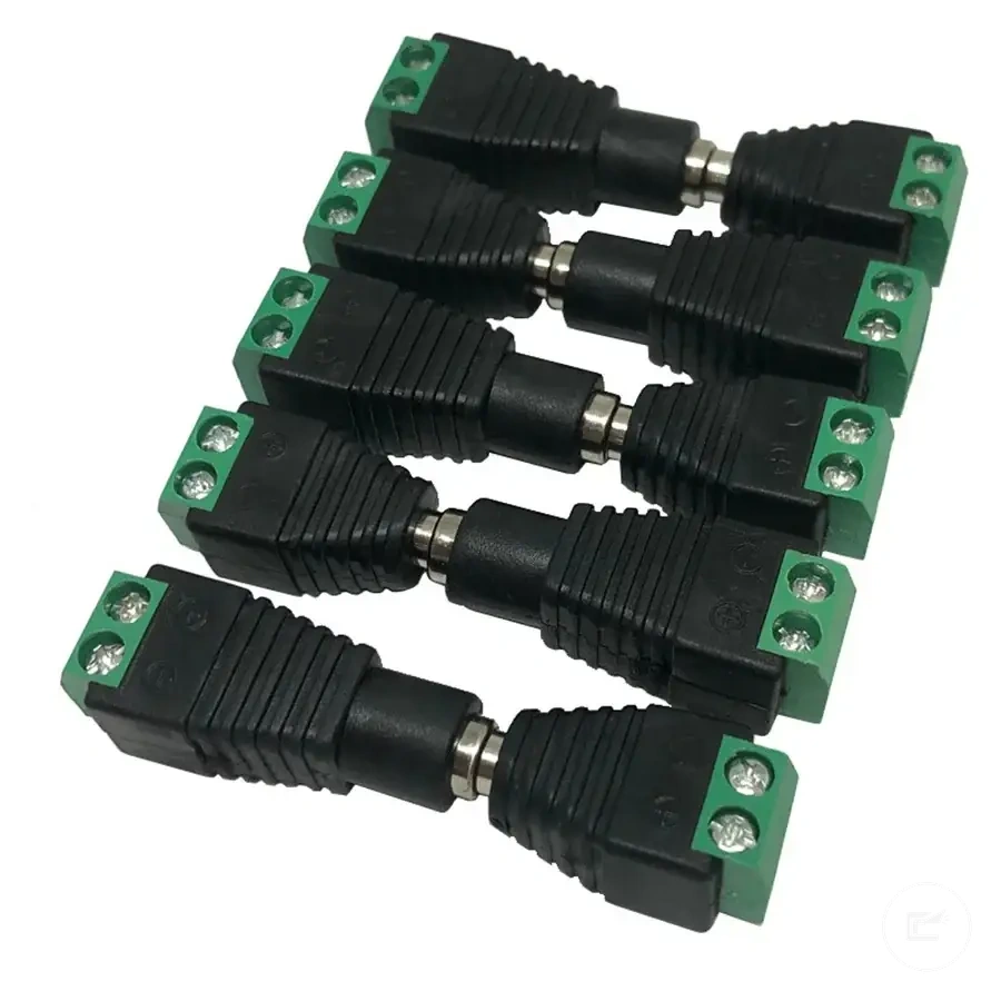
Strip-to-Strip, Strip-to-Wire, and Wire-to-Wire Connectors
When an LED strip setup needs to continue along the same strip, connect to a lead, or extend an existing cable run, the connector format should follow the connection path. A strip-to-strip connector, strip-to-wire connector, and wire-to-wire connector each serve a different joining role within the same system. Physical attributes such as strip width, pin count, and polarity still influence whether the selected format can align correctly. The key compatibility variable in this section is connector format selection by connection path.
Strip-to-Strip, Strip-to-Wire, and Wire-to-Wire Connectors can be organized through the comparison below. The comparison focuses on the job each connector type performs and the conditions that may affect continuity and alignment.
| Connector type | Connection job | Required condition |
|---|---|---|
| Strip-to-strip connector | Joins one LED strip section directly to another strip section | Pin alignment, polarity continuity, and matching strip attributes should align |
| Strip-to-wire connector | Connects an LED strip to a wire lead or extension path | Pin alignment and polarity should match the strip connection points |
| Wire-to-wire connector | Joins cable sections within an extension path | Wire connections should maintain polarity continuity through the circuit path |
Connector format determines the connection job, but compatibility may still depend on strip width, pin count, polarity, and contact alignment. Corner links and extension connectors can follow the same connection-path logic because continuity depends on maintaining the correct electrical relationship across each joined section. For connection execution rather than connector-format selection, see cutting and connecting strips.
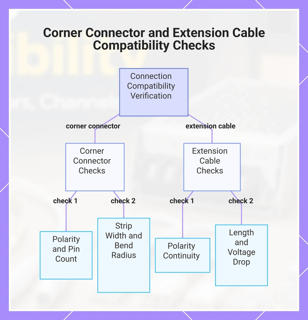
Corner Connectors and Extension Cable Length
Corner connectors and extension cables depend on alignment, polarity, and distance rather than connector shape alone. When an LED strip path changes direction or extends beyond its original position, the corner connector or extension cable should match the connection path and the strip attributes involved. Orientation, pin count, and cable length can influence whether continuity is maintained across the layout. The key compatibility variable in this section is layout-based connection continuity.
Corner Connectors and Extension Cable Length can be organized through the verification checks below. These checks focus on orientation, distance, and placement conditions that may affect compatibility within the same LED strip system.
- Corner connector orientation: Verify that the L connector or corner link follows the intended direction change and maintains polarity alignment.
- Pin count: Check that the connector pins match the strip pin count so electrical paths remain aligned.
- Strip width: Confirm that the connector interface matches the strip width used in the layout.
- Bend radius and placement: Limited space or a tight bend radius may affect fit, depending on the connector design and placement constraints.
- Extension cable polarity: Extension cable conductors should maintain polarity continuity across the extended run.
- Extension length and voltage drop: Longer extension cable runs may increase voltage drop risk, depending on strip voltage, load, cable design, and run conditions.
As introduced in the broader connector section, compatibility should be evaluated through both physical alignment and electrical continuity. A corner connector may fit the layout but still depend on correct pin count and polarity, while an extension cable may require additional review when run distance increases. For connection execution rather than compatibility evaluation, see cutting and connecting strips.
This chart shows the key verification checks for ensuring compatibility of corner connectors and extension cables in LED strip systems, focusing on orientation, polarity, pin count, physical fit, and voltage drop conditions.
Controller Compatibility With LED Strip Type
Controller compatibility depends on matching the LED strip type with the controller output, control signal, voltage, and load requirements. A controller that supports one strip category may not operate another correctly when color channels, pin count, or signal design differ. LED strip type determines which controller functions can be used and which compatibility checks remain necessary. The key compatibility variable in this section is controller-to-strip signal matching.
A controller acts as the control unit between the power source and the LED strip, but its role depends on the strip design it is intended to support. As outlined in accessory parts explained, controller functions vary by strip category rather than by appearance alone. Single-color, tunable white, RGB, RGBW, and addressable strips can require different controller outputs and channel arrangements.
Voltage remains an important compatibility check, but voltage match alone may not be enough. A controller can share the same voltage as an LED strip and still fail to operate it correctly when the color channels, pin count, or control signal do not align with the strip design. This distinction is especially relevant when comparing RGB, RGBW, and addressable LED strip types.
Controller Compatibility With LED Strip Type can be organized through the matching table below. The table highlights the relationship between strip type, controller requirement, common mismatch conditions, and the checks that help verify compatibility.
| Strip type | Controller requirement | Common mismatch | Check |
|---|---|---|---|
| Single-color | Compatible dimmer controller or control unit | Controller output does not match the strip control method | Verify voltage, load, and control compatibility |
| Tunable white | Controller that supports adjustable white channels | Channel support differs from the strip design | Check channel configuration and pin count |
| RGB | Controller that supports RGB color channels | Color channel mismatch | Verify channel output and pin alignment |
| RGBW | Controller that supports RGBW channel output | Missing or incompatible white channel support | Check channel count and control output |
| Addressable | Controller that supports the required data signal | Control signal incompatibility | Verify signal type, voltage, and controller support |
Current rating should also be compared with the expected strip load because controller capacity may vary by design. When voltage, output channels, control signal, and current rating align with the LED strip type, controller compatibility may better support the intended control behavior.
Color Type, Pin Count, and Control Signal
Color type, pin count, and control signal determine whether a controller can operate an LED strip correctly. Controller matching depends on how the strip uses color channels and how those channels connect to the controller output. Single-color, tunable white, RGB, RGBW, and addressable strips use different channel arrangements and signal requirements, making color-control matching the key compatibility variable in this section.
Color Type, Pin Count, and Control Signal can be organized through the comparison below. The comparison shows how channel count, controller output type, polarity, and signal handling influence compatibility conditions for different LED strip types.
| LED type | Controller requirement | Compatibility condition |
|---|---|---|
| Single-color | Controller output designed for single-channel control | Pin count, polarity, and output type should align with the strip design |
| Tunable white | Controller that supports paired white-light channels | Channel type, polarity, and wiring order should match the controller output |
| RGB / RGBW | Controller that supports multiple color channels | Pin count and channel arrangement should correspond to the strip layout |
| Addressable | Controller that supports the required data line and control signal | Signal type, data line handling, and controller compatibility may vary by design |
As introduced in the controller compatibility section, pin count alone does not confirm compatibility. A strip and controller may share a similar connector layout, but controller output type, polarity arrangement, channel count, and control signal still need to align. Addressable strips may require additional verification because data-line communication and signal handling can vary between LED types and controller designs.
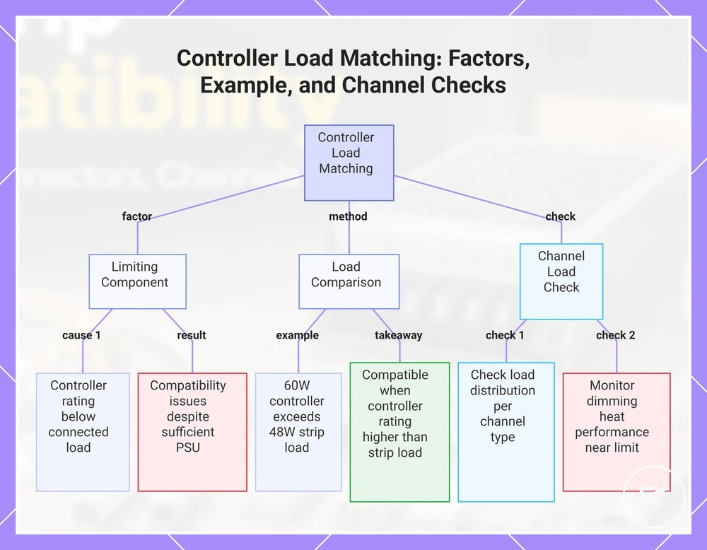
Power Supply and Controller Load Matching
Power Supply and Controller Load Matching depends on the controller being able to handle the electrical load between the power supply and the LED strip. Even when a power supply can support the strip load, the controller may become the limiting component if its voltage, amperage, current rating, or wattage rating is lower than the connected load. Controller load is the key compatibility variable in this section.
Power Supply and Controller Load Matching can be organized through a simple load comparison. The example below highlights how controller rating should be compared with strip load before assuming that power supply capacity alone determines compatibility.
Mini-calculation example: Strip load = 48 W; Controller wattage rating = 60 W; Power supply capacity = 100 W. In this example, the controller rating can accommodate the strip load because the controller limit remains above the connected load. If the controller rating is lower than the strip load, compatibility issues may occur even when the power supply capacity appears sufficient.
Channel load should also be checked for controllers that manage multiple outputs because load distribution may vary by channel type and strip configuration. When controller load approaches its rated limit, dimming behavior, heat risk, or control performance may vary depending on the LED strip and channel load. For broader load-limit considerations and safety boundaries, see power and heat safety.
This chart shows the key factors in matching controller load with power supply and strip load, including a load comparison example and channel load checks.
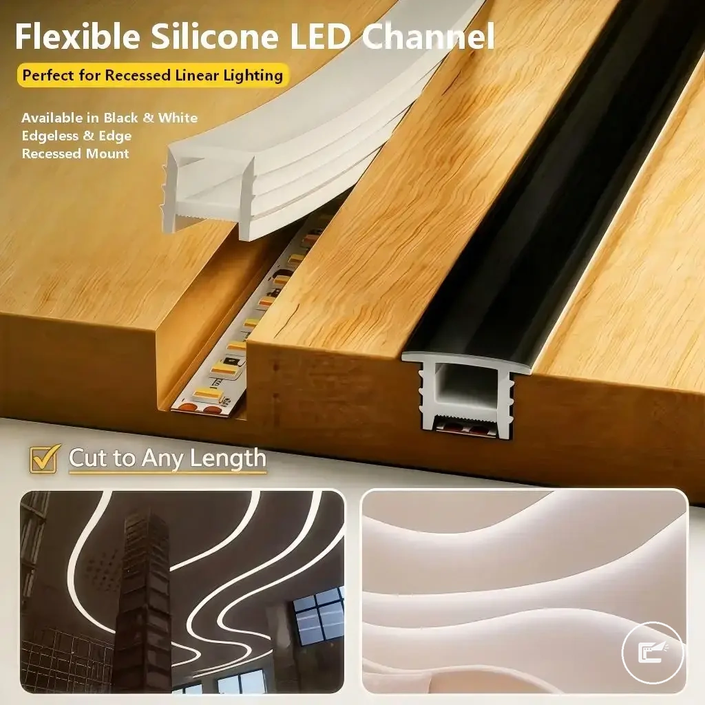
Channel and Diffuser Fit for LED Strips
Channel and Diffuser Fit for LED Strips depends on matching the aluminum channel dimensions to the LED strip and ensuring the diffuser cover has enough clearance above the LEDs. The inner width, internal depth, strip width, and diffuser profile should be evaluated together because physical fit affects strip placement, light spread, and available heat space. Channel and diffuser fit is the key compatibility variable in this section.
An aluminum channel organizes how the LED strip sits within the profile, while the diffuser cover determines the space between the LEDs and the visible surface. Inner width controls whether the strip can fit inside the channel, and internal depth influences diffuser clearance and how light spread may appear through the diffuser cover. Heat dissipation may also vary depending on channel material, airflow, and installation conditions.
Channel and Diffuser Fit for LED Strips is easier to evaluate when the cross-section relationship between width, depth, diffuser clearance, and heat space is visible. The image below clarifies how these attributes interact inside the channel profile.
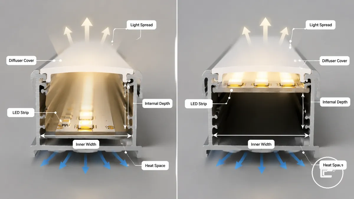
A practical example is a strip that fits within the channel inner width but sits very close to the diffuser cover because of limited internal depth. In that situation, LED density, diffuser profile, and clearance may influence visible hotspots or light spread even though the strip physically fits. When heat space is limited, heat dissipation may also vary by channel design and installation context. For broader heat-related considerations, see power and heat safety.
Channel and Diffuser Fit for LED Strips can be organized through the following fit checks. The table highlights how channel dimensions, strip characteristics, and diffuser clearance influence compatibility.
| Channel factor | Strip condition | Effect on fit or light | Check |
|---|---|---|---|
| Inner width | Strip width approaches channel width | May affect physical fit | Compare channel width and strip width |
| Internal depth | Limited space above the LEDs | May affect diffuser clearance and hotspots | Check LED-to-diffuser distance |
| Diffuser profile | Different diffuser designs | May influence light spread | Verify profile compatibility |
| LED density | Higher concentration of LEDs | May change hotspot visibility | Assess depth and diffuser relationship |
| Adhesive clearance | Strip backing and mounting surface | May affect seating inside the channel | Confirm available installation space |
| Mounting clips and heat space | Channel installation arrangement | May influence fit and heat dissipation | Review profile and mounting conditions |
Inner Channel Width, Depth, and Strip Placement
Inner channel width, depth, and strip placement depend on comparing actual channel dimensions with the LED strip dimensions before the diffuser is attached. The inner channel width should be checked against PCB width and strip clearance, while channel depth should be reviewed against LED height, adhesive base thickness, and available placement space. Actual dimensions determine whether the strip can sit correctly within the profile, making dimensional clearance the key compatibility variable in this section.
Inner Channel Width, Depth, and Strip Placement can be organized through the sizing checks below. The table focuses on local measurements that help verify strip placement conditions before diffuser attachment.
| Measurement | What to verify | Why it matters |
|---|---|---|
| Inner channel width | Compare internal width with PCB width | Helps determine strip clearance and placement room |
| PCB width | Check strip width against channel dimensions | May affect whether the strip can sit within the profile |
| Solder-pad clearance | Review clearance around connection points | May influence local fit conditions |
| LED height | Compare component height with channel depth | May affect available vertical clearance |
| Adhesive base | Check backing thickness and seating position | May influence strip placement inside the channel |
| Channel depth | Verify profile depth and strip clearance | Helps assess placement space before diffuser attachment |
| Mounting clip space | Check clip position and available room | May influence placement tolerance depending on profile design |
As introduced in the parent channel section, dimensional checks should focus on measurable clearance rather than assumptions about compatibility. Placement tolerance, solder-pad clearance, LED height, and mounting clip space can vary by manufacturer dimensions and profile shape, so fit should be verified through actual measurements rather than assumed compatibility.
Diffuser Depth, Light Spread, and Heat Space
Diffuser depth affects light spread, heat space, and clearance inside the LED strip channel. The distance between the LEDs and the diffuser cover can influence how visible hotspots appear, while opacity and LED density may change how evenly light is diffused. The snap-fit cover also needs enough clearance to close without pressing against the strip, making diffuser clearance the key compatibility variable in this section.
Diffuser Depth, Light Spread, and Heat Space can be organized through the comparison below. The comparison shows how shallow and deeper diffuser clearance may affect hotspot visibility, cover fit, and available heat space.
| Diffuser clearance | Condition | Possible outcome |
|---|---|---|
| Shallow clearance | LEDs sit close to the diffuser cover | Hotspots may be more visible, and snap-fit clearance may be reduced |
| Deeper clearance | More distance separates the LEDs from the diffuser cover | Light spread may appear softer, depending on opacity, LED density, and channel depth |
| Limited heat space | Channel depth leaves little room around the strip and cover | Heat space may need closer review because clearance and material conditions can vary |
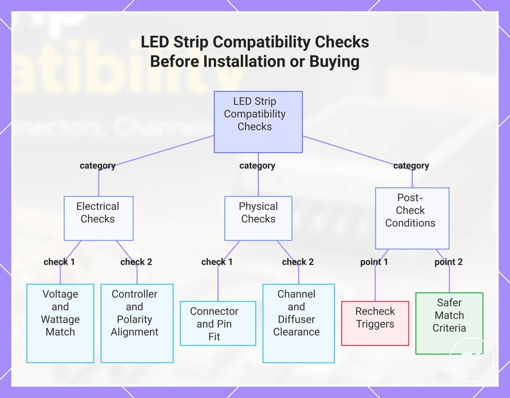
Compatibility Checks Before Installation or Buying
Compatibility checks before installation or buying should verify the LED strip, power supply, controller, connectors, extensions, and channel components as one connected system. A component may appear suitable but still create compatibility issues when voltage, ratings, pin layout, polarity, or physical clearances do not align. This compatibility checklist consolidates the final decision points before selection or installation and controls the compatibility variable for this section.
The compatibility checklist brings together the power, connector, controller, and channel checks covered earlier without repeating their detailed explanations. Each item uses a condition and a decision cue to help verify compatibility before a component is chosen or installed.
If a setup already shows flickering, dead sections, uneven control behavior, overheating signs, or unexplained power issues, compatibility checks should pause until the cause is reviewed. For unresolved wiring or signal concerns, see troubleshooting connection problems before assuming that a different accessory is required.
- Voltage: If the strip, power supply, and controller voltage labels match, continue verification; if they differ, recheck the component selection.
- Power supply wattage: If available capacity exceeds expected load, continue evaluation; if capacity appears limited, review the power requirement again.
- Controller rating: If the controller rating supports the connected load, continue; if ratings appear lower than expected demand, reconsider the match.
- Connector width: If connector width matches strip width, continue; if fit appears loose or restricted, verify dimensions.
- Pin count: If pin count aligns with the strip configuration, continue; if pin layouts differ, confirm compatibility before proceeding.
- Polarity: If polarity markings remain aligned throughout the connection path, continue; if markings are unclear, verify orientation before use.
- Extension length: If cable length suits the layout, continue; if the run becomes longer, review potential voltage-related limitations.
- Channel size: If channel size accommodates the strip and mounting space, continue; if clearance is limited, review fit conditions.
- Diffuser clearance: If diffuser clearance remains adequate above the LEDs, continue; if clearance is shallow, reassess fit and light-spread expectations.
- Mounting method and safety limits: If mounting conditions support stable placement and heat space, continue; if strain, damage, or heat concerns appear, review the setup before installation.
Recheck compatibility when labels are missing, when a single component has been replaced without reviewing the rest of the system, or when changes affect extension length, channel size, diffuser clearance, or power requirements. A safer component match may be appropriate when ratings are close to their limits, polarity cannot be confirmed, or physical fit remains uncertain. For additional decision support before choosing a power approach, see power method comparison.
The products below are useful examples for comparing available options. Before buying, check that the compatibility criteria, key features, and product details match your needs.
This chart groups the essential compatibility checks for LED strip systems into electrical, physical, and post-check conditions to help verify component alignment before installation.