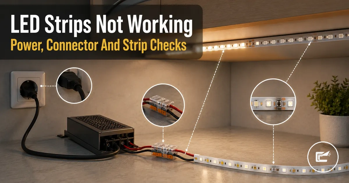
Under Cabinet LED Strip Lights Not Working
When under cabinet LED strip lights are not working, the cause is often linked to power delivery, connection points, control components, or strip damage rather than the LED strip alone. A failure may appear as flickering, shutdown, no response, or a dead section, and the exact cause depends on the setup, including the power supply, driver, connector, controller, dimmer, cut point, or copper pads.
Under cabinet LED strip failure is a system-level fault that can involve the LED strip, power supply, driver, connector, controller, dimmer, cut point, or copper pads. The diagnostic context for these connected components sits within home LED strip and cabinet lighting accessories.
Visible symptoms often provide the first useful clue. When under cabinet LED strip lights show flickering, a delayed response, repeated shutdown, or an isolated dead section, the fault may relate to voltage delivery, connector contact, polarity alignment, controller or dimmer response, or a failure after reconnection at a cut point. This page focuses on troubleshooting rather than serving as a full installation guide, compatibility guide, or safety checklist, and the next step is to sort faults by symptom pattern before testing individual components or considering replacement.
If the failure includes overheating, a burning odor, damaged wiring, or other unusual electrical symptoms, stop troubleshooting before attempting normal fixes. In those situations, repair or replacement decisions may depend on the condition of the affected components and the overall setup.
Failure Symptoms Before Testing the LED Strip
When failure symptoms appear, the likely cause is often easier to narrow down before testing begins. Visible patterns such as no light, partial light, flickering, sudden shutoff, post-cut failure, or post-connection failure can point toward a likely affected part without confirming a final diagnosis. These failure symptoms help determine the first check and the most useful diagnostic direction.
A new installation that never worked may indicate a different fault area than a strip that worked previously and then stopped. New-installation issues may relate to setup conditions, while later failures may point toward a change in power delivery, contact quality, controller response, or strip condition. Because the same symptom pattern can come from more than one fault area, avoid assuming a single likely cause without further testing.
Failure Symptoms Before Testing the LED Strip should be sorted before component testing begins. The image below highlights visible symptom categories and helps organize the first diagnostic direction for each fault sign.
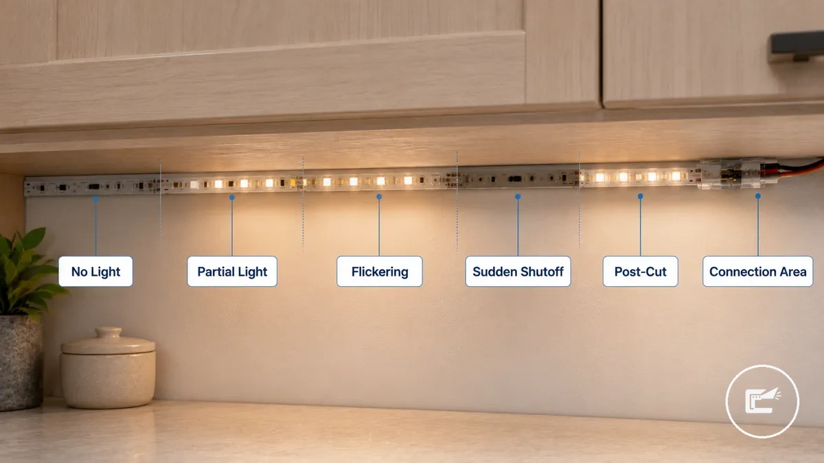
Failure Symptoms Before Testing the LED Strip can narrow the first check before deeper troubleshooting. Use the checklist to connect each symptom pattern with a likely affected part and a diagnostic direction.
- No light: Likely affected part may be the power supply, connector, or controller; first check whether any strip response is present.
- Partial light: Likely affected part may be a strip section or connection area; first check where the visible problem starts.
- Flickering: Likely affected part may involve a loose contact, dimmer behavior, or power condition; first check whether the light behavior changes over time.
- Sudden shutoff: Likely affected part may relate to power delivery or controller response; first check whether the fault follows a specific operating condition.
- Post-cut failure: Likely affected part may involve the cut point, copper pads, or polarity alignment; first check the modified section of the strip.
- Post-connection failure: Likely affected part may be the connector or reconnection point; first check the contact area where the change was made.
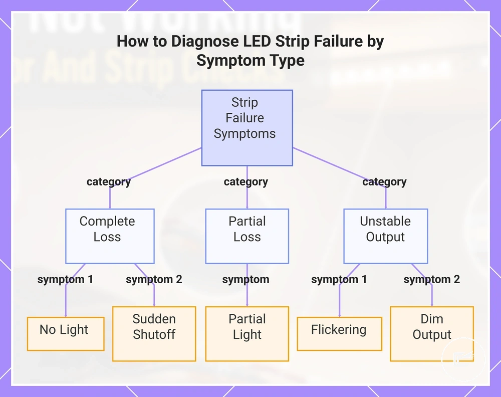
No Light, Partial Light, Flickering, and Sudden Shutoff
When no light, partial light, flickering, or sudden shutoff appears, the symptom often helps separate complete power loss from unstable current or local strip failure. Whole-strip failure affects the entire strip response, while local section failure is limited to a dead section or strip segment.
- No light: The affected zone is the entire strip; a full blackout may suggest power loss because no strip response is visible, pointing toward a whole-strip failure condition.
- Partial light: The affected zone is a dead section or strip segment; this often points to a local section failure because only part of the strip remains affected.
- Flickering: The affected zone may be the whole strip or one area; intermittent flicker may suggest unstable current, a loose contact, or dimmer-related behavior.
- Dim output: The affected zone is often broader than a single dead section; a light drop may suggest a condition affecting overall strip response rather than one isolated area.
- Sudden shutoff: The affected zone is commonly the whole strip; shutoff after warming may suggest a heat- or overload-related condition and is worth checking further.
This chart groups LED strip failure symptoms into three categories to help identify the underlying cause.
Problems After Cutting, Extending, or Reconnecting the Strip
When a failure appears after cutting, extending, or reconnecting the strip, the modified point is the first place to inspect. These symptoms often suggest a local fault near the cut point, extension cable, or reconnection area, so attention should start at the modified point.
- Cut point: Check whether the cut follows the marked line; an issue at the cut point may create a dead section beyond the modified area.
- Copper pad: Check the copper pad at the strip end; poor contact at this area may reduce light output or affect part of the strip.
- Connector fit: Check whether the connector fit is secure; weak contact at the reconnection area may contribute to flicker or intermittent operation.
- Polarity: Check polarity at the modified point; incorrect alignment may result in no light from the affected section.
- Extension cable: Check for a loose connection where the extension cable joins the strip; this condition may cause flicker or a dead section.
- Reconnecting: Check the connector clip or reconnection area first; a local fault here may appear immediately after reconnecting.
Power Source, Driver, and Voltage Problems
When an LED strip has no light, dimming, flicker, shutdown, or overheating, the power source or driver may be part of the fault. Power delivery should be checked before replacing visible parts because unstable power can make a working strip look faulty. This section focuses on power stability.
Power Source, Driver, and Voltage Problems usually depend on whether the voltage, wattage, power supply capacity, and load match the strip setup. A mismatched supply may prevent a response, an undersized driver may cause dimming or shutdown under load, and a loose adapter may create flicker because contact is not stable.
Power Source, Driver, and Voltage Problems are easier to inspect when the power path is visible. The image labels the power supply, driver, voltage label area, and strip input connection, and the table diagnoses common power faults by symptom and check.
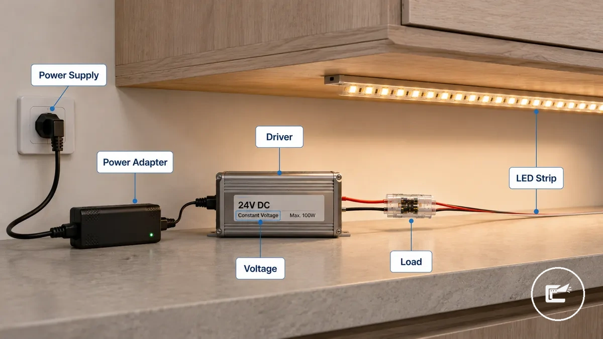
| Power part | Attribute or condition | Symptom it can cause | What to check next |
|---|---|---|---|
| Power adapter | Loose adapter or unstable connection | Flicker, dimming, or no light | Check whether the adapter connection is seated firmly before testing other parts. |
| Power supply | Voltage mismatch with the strip rating | No light, weak output, or unusual strip response | Compare the visible supply label with the strip setup before continuing. |
| Driver | Wattage capacity may be too low for the connected load | Dimming or shutdown during use | Check whether the driver capacity fits the connected strip length and accessories. |
| Power run | Overloaded run or excessive load on one supply | Shutdown, heat, or unstable output | Stop troubleshooting if overheating appears, then review the load path. |
| Driver | Failed driver or inconsistent output | No response, flicker, or repeated shutdown | Check whether the strip responds with a known suitable power source before replacing parts. |
Voltage and capacity should match the strip setup before deeper component testing; use compatibility checks when the label, load, or driver condition is unclear.
Connector Contact, Polarity, and Fit Faults
When an LED strip has no light, flicker, or a dead section, a connector fault may interrupt current even if the strip and power supply are still usable. Connector contact, polarity, and fit should be checked before assuming the strip has failed. Connector faults can mimic a dead strip.
Connector Contact, Polarity, and Fit Faults often come from poor contact at the contact surface, reversed polarity, strip width mismatch, pin alignment issues, or insufficient clamp pressure. A connector clip may appear connected while the copper pad is only partially engaged, and a loose clip may create intermittent symptoms because contact is unstable.
Connector Contact, Polarity, and Fit Faults are easier to diagnose when the contact area is visible. The image below labels the contact points that commonly cause no-light or flicker symptoms.
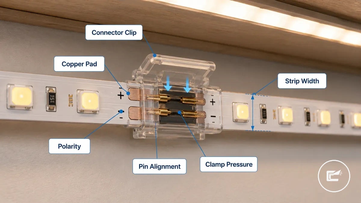
Connector fit, polarity, and contact pressure are the main checks. This checklist verifies physical contact and fit before deciding whether the issue is more likely related to poor contact or an incompatible fit.
- Connector contact: Check whether the contact surface fully reaches the copper pad; poor contact may cause no light.
- Reversed polarity: Check polarity marks at the strip end; reversed polarity may prevent normal strip response.
- Strip width: Check whether the connector matches the strip width; a fit fault may lead to intermittent failure.
- Pin alignment: Check whether pin alignment matches the contact point; misalignment may create a dead section or no response.
- Clamp pressure: Check whether clamp pressure holds the strip securely; a loose clip may contribute to flicker.
- Copper pad exposure: Check whether enough copper pad is exposed for contact; limited contact area may affect current flow.
Poor contact usually involves a connection that may work intermittently, while an incompatible fit often involves strip width or pin alignment that prevents reliable contact from the start.
Controller, Dimmer, Remote, and Reset Issues
When an LED strip responds inconsistently, changes color incorrectly, will not dim, or ignores the remote, the issue may come from the control path rather than the strip itself. A controller, dimmer, remote, or reset state can affect strip behavior even when power is present. Bypass behavior can help separate control failure from power loss.
If a remote control has no response, the battery, signal path, pairing state, or receiver condition may be worth checking. If a dimmer causes flicker or irregular dimming, the load rating or dimmer response may be part of the issue. A controller or control module may also affect color change or output channel behavior when the strip responds differently than expected.
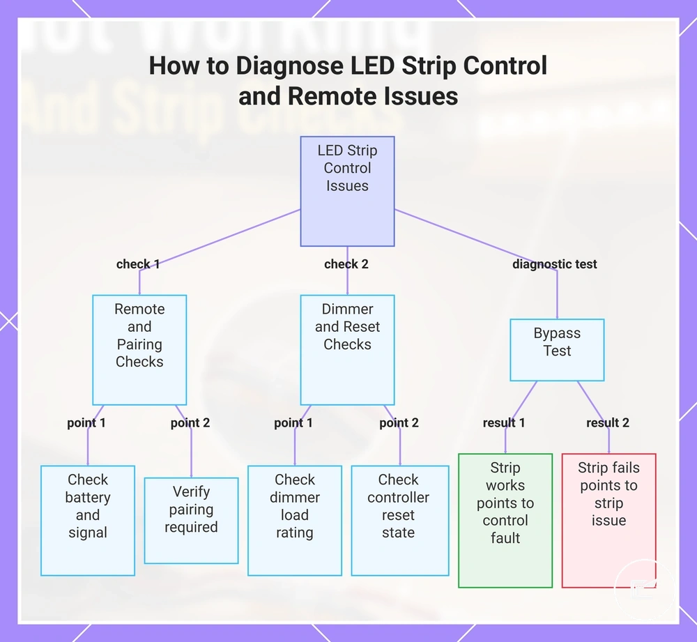
If the strip works when bypassing the controller and connecting through direct power, the control device may be involved in the fault path. If the strip still fails with direct power, the condition may be outside the controller, dimmer, remote, or reset state. Controller, Dimmer, Remote, and Reset Issues can be checked with the simple sequence below, which applies only when a control device exists in the setup.
- Remote: Check the battery and signal response. If the remote shows no response, the issue may involve the battery, signal path, or receiver.
- Pairing: Check whether pairing is required for the controller or remote. If pairing is lost, the strip may not respond to commands.
- Reset: Check whether the controller is in an unexpected reset state. If settings were changed, strip behavior may differ until the control state is restored.
- Dimmer: Check the dimmer and load rating. If flicker or unstable dimming appears, the dimmer condition may contribute to the symptom.
- Bypass: Check strip behavior with direct power when appropriate. If the strip works when bypassed, the result may point toward a controller, dimmer, remote, or output channel issue rather than the strip itself.
This chart shows the main checks for control-related LED strip issues, including remote, dimmer, reset, and bypass tests.
Cut Points, Copper Pads, and Reconnection Failures
When an LED strip stops working after being cut, extended, or reconnected, the fault is often located at the modified segment. A cut point, copper pads, solder joint, connector tooth, or polarity mark may affect continuity and lighting output when the connection is incomplete or misaligned. The modified segment is the highest-priority inspection zone.
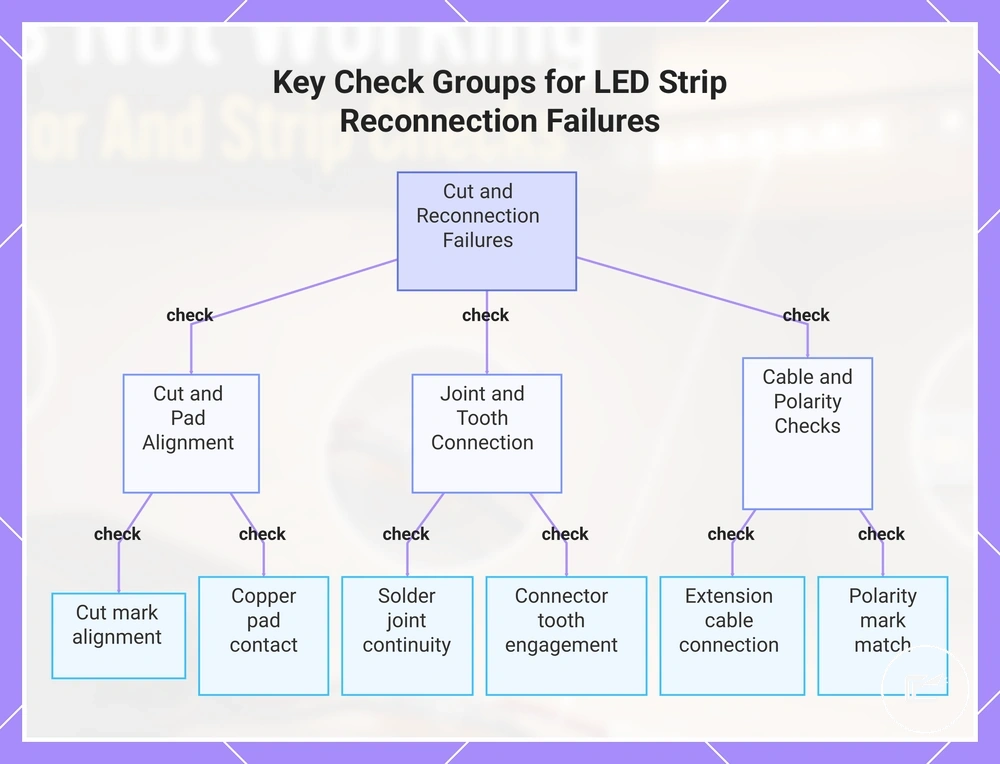
Cut Points, Copper Pads, and Reconnection Failures often begin with a visible condition near the connection point. A cut mark that does not align with the intended connection area, a copper pad with poor contact, a solder joint with interrupted continuity, or a reversed polarity mark may cause no light, flicker, or a dead section. When continuity is interrupted at the strip end or extension cable connection, the affected area is usually local rather than spread across the entire strip.
A repairable reconnection failure may involve a contact problem at the pad area, solder joint, connector tooth, or extension cable connection. A damaged strip segment may show visible strip damage or a condition that remains unchanged after the connection point is checked. Cut Points, Copper Pads, and Reconnection Failures can be inspected with the checklist below, which verifies the modified segment without turning troubleshooting into a full cutting tutorial.
- Cut mark: Check whether the cut mark aligns with the intended connection area; a poor cut location may interrupt continuity and result in no light.
- Copper pads: Check whether the copper pads remain exposed and make proper contact; limited contact may reduce or stop lighting output.
- Solder joint: Check whether the solder joint appears continuous; a local failure at the joint may interrupt power flow to the next segment.
- Connector tooth: Check whether the connector tooth reaches the copper pad correctly; poor engagement may create flicker or a dead section.
- Extension cable: Check the extension cable connection point; a loose or incomplete connection may affect continuity and strip response.
- Polarity mark: Check whether the polarity mark matches the connected extension cable or strip end; a reversed connection may result in no output from the local segment.
When the fault pattern remains limited to the modified segment, further context about cutting and connection issues may help clarify broader connection-related conditions.
This chart groups the most common inspection points for diagnosing LED strip failures after cutting or reconnecting.
Damaged Strip Sections and Dead LEDs
When a damaged strip section or dead LEDs stay dark after connection checks, the strip material or LED section may be damaged. Local failure can come from LED chips, a copper trace, a resistor area, adhesive backing stress, heat exposure, or bend damage. This separates likely strip damage from poor contact.
Under cabinets, visible strip damage may appear as a cracked strip, burnt marks, water exposure, sharp bends, loose adhesive backing, or heat-stressed areas. These signs matter because a damaged section can create a dead section, color loss, flicker, or a replacement need depending on where the local failure appears.
Damaged Strip Sections and Dead LEDs should be judged by local symptoms and visible condition after connection points have been checked. Replacement depends on the damaged area, whether the symptom repeats, and whether the affected strip segment can be isolated.
| Visible condition | Likely affected area | Symptom | Repair or replacement signal |
|---|---|---|---|
| Dead segment | LED chips or copper trace | Dead section or no output in one area | May need replacement if the segment stays dark after contact checks. |
| Cracked strip | Copper trace or resistor area | Color loss, flicker, or local failure | May point toward strip damage when the crack crosses the active path. |
| Burnt mark | LED chips, resistor area, or nearby trace | Flicker, dimming, or dead LEDs | May create a replacement need if the mark is near the failed section. |
| Water exposure | Pad area, LED chips, or copper trace | Intermittent output, color loss, or dead section | May require replacement when the same local fault repeats after drying and reconnection checks. |
| Sharp bend | Copper trace or strip backing | Dead segment, flicker, or color loss | May indicate bend damage if the symptom starts at the bend point. |
| Heat-stressed area | LED chips, resistor area, or adhesive backing | Dimming, flicker, or local failure | May support replacement when heat exposure leaves visible marks or recurring output loss. |
Testing the Fault Before Replacing Parts
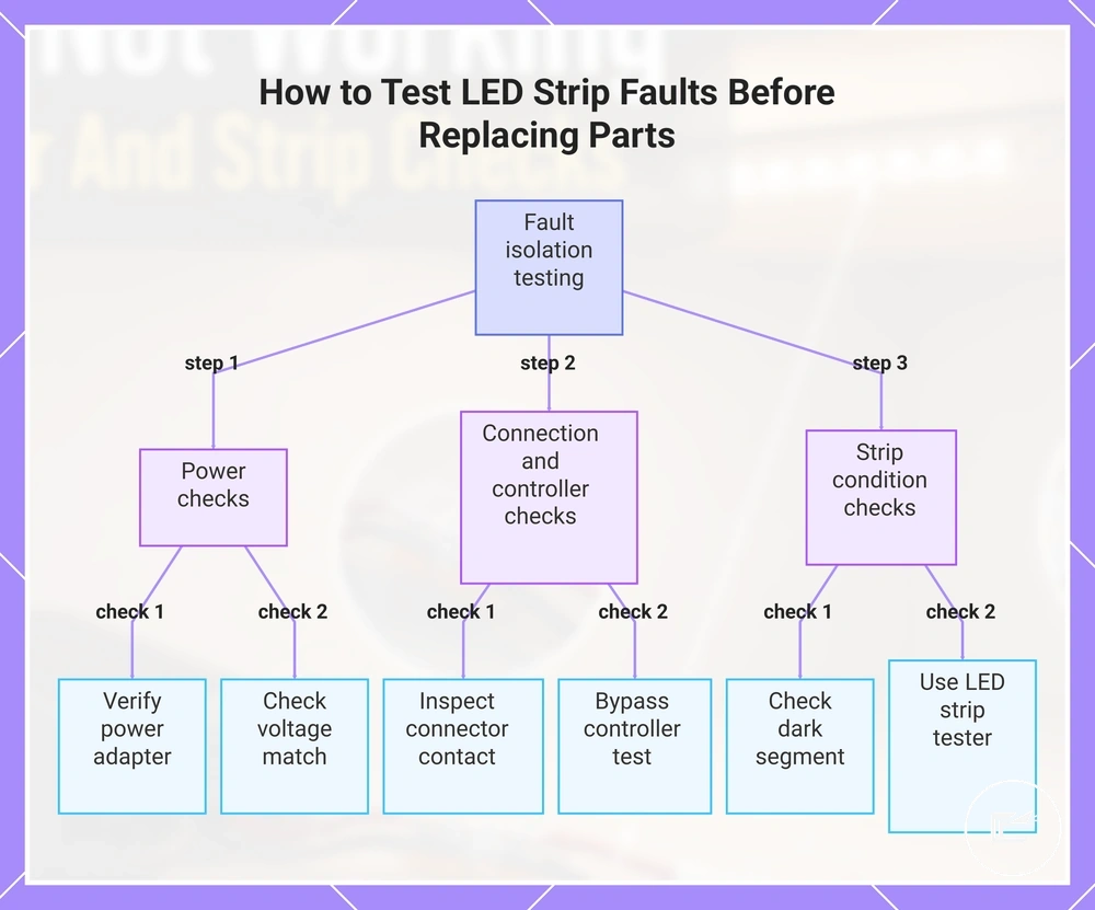
Testing the fault before replacing parts starts with isolating the likely failed component instead of assuming the LED strip is damaged. The safest approach is to move from power checks to connection checks, then controller checks, and finally strip condition checks. Testing should isolate one component at a time.
Testing the Fault Before Replacing Parts uses a simple sequence to isolate components before replacement decisions are made. Follow the steps below using safe checks only, and avoid unsafe live-wire work or advanced electrical repair procedures.
- Power presence: Verify the power source using a known-good adapter when available. If the strip responds with the known-good adapter, the original power source may be part of the fault.
- Voltage match: Check whether the visible power label matches the strip requirements. If the voltage match appears incorrect, the power setup may affect normal strip response.
- Connector continuity: Inspect the connector, copper pad contact, and connection points. If contact improves and the strip responds, the fault may be related to connector continuity rather than the strip itself.
- Controller bypass: Use a direct connection check when the setup includes a controller. If the strip responds when the controller is bypassed, the result may point toward a control fault rather than strip damage.
- Strip segment response: Observe whether one strip segment remains dark while other sections respond. A dead section may help isolate the fault to a local segment rather than the entire strip.
- LED strip tester: Use an LED strip tester when available and appropriate for the strip type. If the tester produces a response, the result may help narrow the fault to another component in the system.
These troubleshooting checks help separate fault diagnosis from setup guidance. For broader setup instructions, refer to the installation process. If the fault remains unclear after isolating each component, replacement decisions should depend on the results of the checks rather than assumptions about a single part.
This chart shows the recommended step-by-step testing sequence to isolate the faulty component in an LED strip system, starting with power checks and ending with strip condition checks.
When a Connector, Power Supply, Controller, or Strip Needs Replacement
Replacement depends on whether troubleshooting points to a specific failed part, visible condition, compatibility issue, or repeatable failure sign. Connector, power supply, controller, dimmer, extension cable, and strip section decisions should be based on consistent evidence rather than a single symptom. Replacement should follow evidence, not guessing.
A repairable fault may not require replacement. For example, a connector with poor contact may respond after reconnection or adjustment, while a damaged component or aging component may continue showing the same failure sign even after compatibility and connection checks are completed.
When a Connector, Power Supply, Controller, or Strip Needs Replacement becomes easier to assess after the likely failed part has been isolated. The table below organizes replacement signals, replacement conditions, and replacement risks by component. Compatibility and repeatability matter before deciding to replace any part.
| Part | Replacement signal | Check before replacing | Risk of replacing too early |
|---|---|---|---|
| Connector | Poor contact remains after adjustment or reconnection | Verify contact quality and connection condition | A repairable fault may be mistaken for a replacement condition |
| Power supply | Failure sign remains after checks and a failed driver or supply is suspected | Confirm voltage match and power response | The power supply may be replaced when another fault is causing the symptom |
| Controller or dimmer | Control failure remains after a bypass test | Verify controller bypass results and strip response | A strip condition issue may be confused with a controller or dimmer fault |
| Extension cable | Repeat symptom appears at the cable path or connection area | Confirm continuity and connection condition | A nearby connector fault may be overlooked |
| Strip section | Visible damage or a repeat symptom affects the same area | Check strip section condition and local response | A connection-related issue may be mistaken for strip damage |
Replacement timing depends on the failure sign, compatibility, and symptom repeatability. For broader timing considerations and aging-related context, refer to the replacement and lifespan guidance.
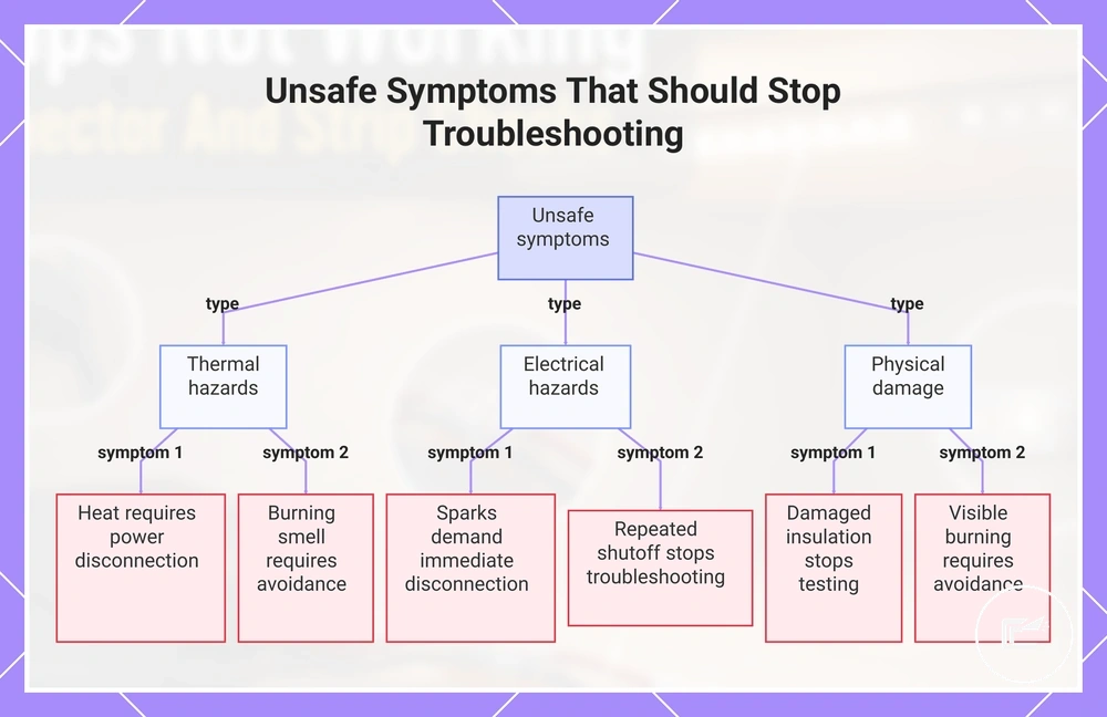
Unsafe Symptoms That Should Stop Troubleshooting
Unsafe symptoms stop normal troubleshooting. When heat, a burning smell, sparks, or damaged insulation appear, the priority changes from fault finding to risk reduction. Unsafe symptoms stop normal troubleshooting.
Normal low-voltage troubleshooting involves routine checks of connections, controls, and strip condition. The boundary changes when warning signs suggest an unsafe condition rather than a normal fault. In those situations, disconnect power, stop testing, and avoid further power-related checks.
Unsafe Symptoms That Should Stop Troubleshooting can be recognized with the warning checklist below. These stop-signals identify when immediate action is more important than continued diagnosis. For additional escalation criteria, refer to the safety warning signs.
- Heat: Strong heat from a power supply, controller, connector, or strip area may indicate an unsafe condition. Disconnect power and stop troubleshooting.
- Burning smell: A burning smell from any component indicates a potential risk condition. Disconnect power, avoid reuse, and seek qualified help.
- Sparks: Sparks at a connector, cable, power supply, or strip area are a stop signal. Disconnect power immediately, avoid reuse, and seek qualified help.
- Damaged insulation: Damaged insulation on a cable or power-related component may increase risk. Disconnect power, avoid reuse, and stop testing.
- Repeated shutoff: If repeated shutoff continues, especially near the power supply or control path, the condition may require safety escalation. Disconnect power and stop troubleshooting until the cause is assessed.
- Visible burning or melting: Burn marks, melted material, or similar damage on any component indicate an unsafe condition. Disconnect power, avoid reuse, and seek qualified help.
This chart lists the warning signs that require immediate action during LED strip troubleshooting, including thermal, electrical, and physical damage indicators.