Installing LED Strip Lights Under Cabinets
Installing under cabinet LED strip lights starts with planning the strip run on the cabinet underside, confirming a suitable low voltage power supply, and choosing a mounting method that fits the installation conditions. The process can affect light output, cable route visibility, and future access to components. This page focuses on practical installation decisions for home LED strip and cabinet lighting accessories while keeping the scope limited to preparation, connection checks, placement, and mounting considerations.
The correct installation depends on cabinet surface conditions, strip type, power method, connector design, heat conditions, and cable route planning. A clean and dry cabinet underside may support adhesive mounting, while longer runs, heavier mounting components, or more complex layouts may require additional mounting support, extension cable planning, or connector checks before final installation.
Before mounting begins, it is useful to verify power access, voltage compatibility, connector orientation, and the planned route between the power supply and the strip. Early testing can help identify connection issues, uneven light output, or cable strain while adjustments remain easy to make.
Low voltage installations are often suitable for careful DIY work when component compatibility and cable routing are clear. If the installation involves mains wiring, hidden wiring, hardwired drivers, or uncertain electrical capacity, assessment by a qualified electrician may be appropriate.
Under Cabinet Installation Checks Before Starting
Under cabinet installation suitability depends on cabinet condition, power access, strip compatibility, and working conditions before mounting begins. A short pre-installation review can reduce the risk of poor adhesion, difficult cable routing, or power connection problems. Checking these criteria early helps determine whether a DIY installation is practical or whether additional preparation may be needed.
Focus on the cabinet surface, outlet location, driver position, voltage compatibility, strip run length, and any planned drilling or hardwiring. Each condition can affect installation fit, cable management, and access for future maintenance.
- If the cabinet surface is not clean and dry, adhesive mounting may be less reliable and surface preparation may be needed before installation.
- If power access is far from the installation area, confirm that the cable route remains practical and does not create visible or strained connections.
- If a low voltage kit uses a separate driver, check that the driver location remains accessible after installation.
- If strip voltage, connector type, and power supply specifications do not match, compatibility issues may occur during testing or operation.
- If the planned run length is longer than expected, verify the layout before mounting to reduce the risk of rework.
- If drilling is required, inspect the cabinet material and surrounding area to reduce the risk of unintended damage to the cabinet underside or concealed components.
When evaluating installation risks, start with simple checks before mounting any strip. Reviewing safety before installation can help identify conditions that may require additional planning, particularly when voltage compatibility, connector selection, heat spacing, or cable routing remain uncertain.
A low voltage setup with a plug-in kit may be suitable for DIY installation when power access, cable routing, and component fit are clear. If hardwiring, uncertain power loads, damaged cabinets, or mains electrical work are involved, assessment by a qualified electrician or other qualified professional may be appropriate.
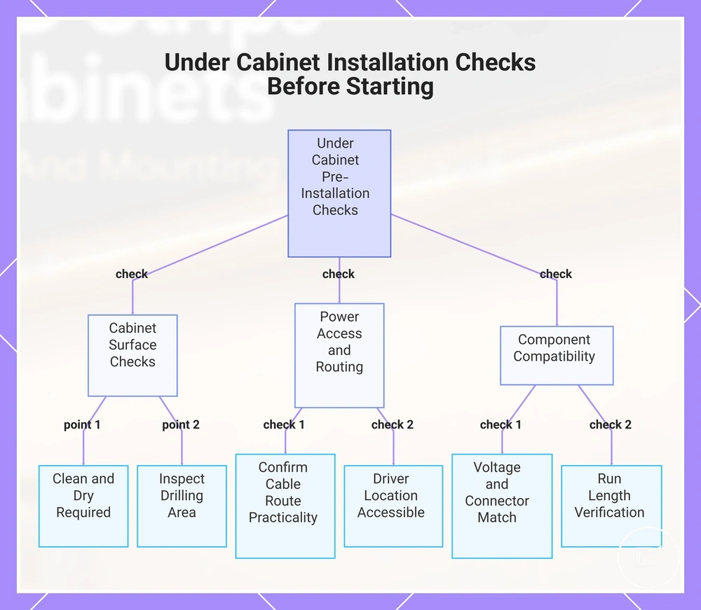
This chart shows the key pre-installation checks for under cabinet lighting, covering cabinet surface, power and cable routing, and component compatibility.
When DIY Installation Is Suitable
DIY installation is usually suitable when a low voltage kit uses a plug-in connection and the cabinet surface, power access, and component compatibility are clear. This applies to cabinet lighting installations where the power route can be planned easily and the installation does not depend on hardwiring.
- If the cabinet surface is clean and dry, adhesive mounting may be easier to position and assess before final placement.
- If an outlet is accessible near the installation area, power access and cable route planning are often simpler.
- If the low voltage kit includes a matching power supply, driver, and connector system, compatibility checks are usually more straightforward.
- If the strip follows a simple straight run, placement and fit may be easier to confirm before mounting.
- If manufacturer-supported connectors are used, connection points may be easier to inspect during testing.
A low voltage setup can be a suitable choice for DIY installation when these conditions are met. If hardwiring, uncertain electrical loads, or wiring modifications are involved, the suitability decision may change and assessment by a qualified professional may be appropriate.
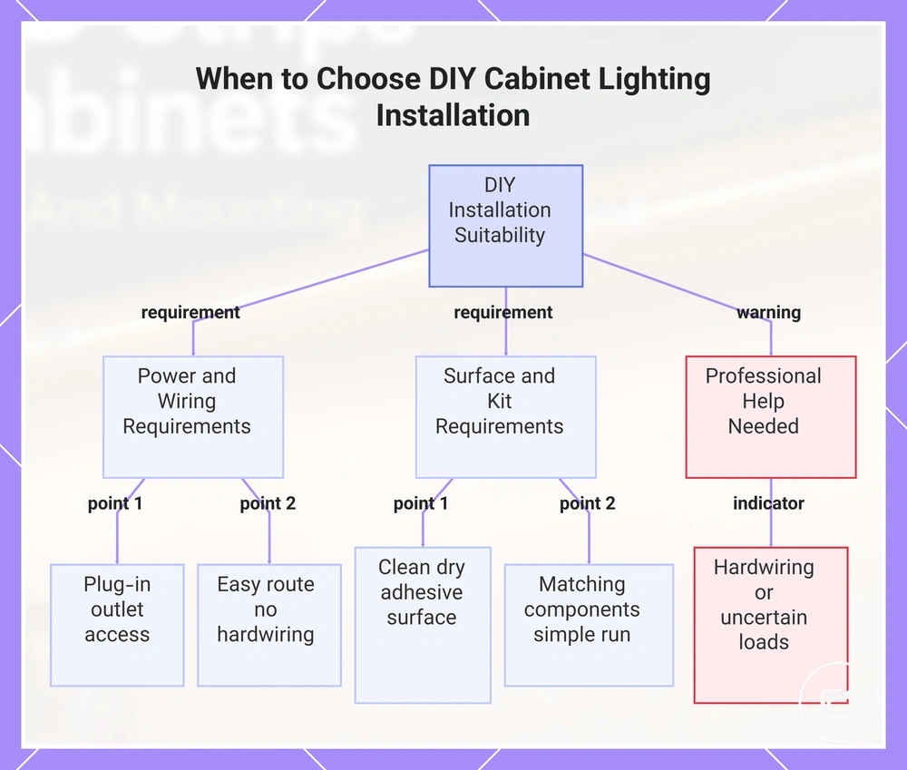
This chart shows the key conditions that make low voltage cabinet lighting suitable for DIY installation and identifies when professional assessment is needed.
When an Electrician Is Needed
An electrician is needed when the installation involves mains wiring, a hardwired driver, hidden wiring, code-sensitive routing, or uncertain electrical capacity. These conditions fall outside the low voltage boundary and can affect a safe installation.
- If hardwiring is required instead of a plug-in connection, a qualified electrician should handle the mains connection decision.
- If hidden wiring or a concealed junction is present, the installation should be treated as an escalation point rather than a DIY task.
- If damaged wiring is discovered, stop the installation and seek professional assessment before proceeding.
- If electrical capacity is unclear or an overload condition may exist, further evaluation is needed before adding cabinet lighting equipment.
- If hardwired driver specifications cannot be confirmed, compatibility and installation risk may be difficult to assess.
- If cable routing depends on concealed spaces or code-sensitive routing, a licensed professional may be needed to determine a suitable approach.
The low voltage boundary helps separate plug-in cabinet lighting installations from situations that involve mains wiring or uncertain electrical conditions. When these escalation signals are present, a qualified electrician is the appropriate next step.
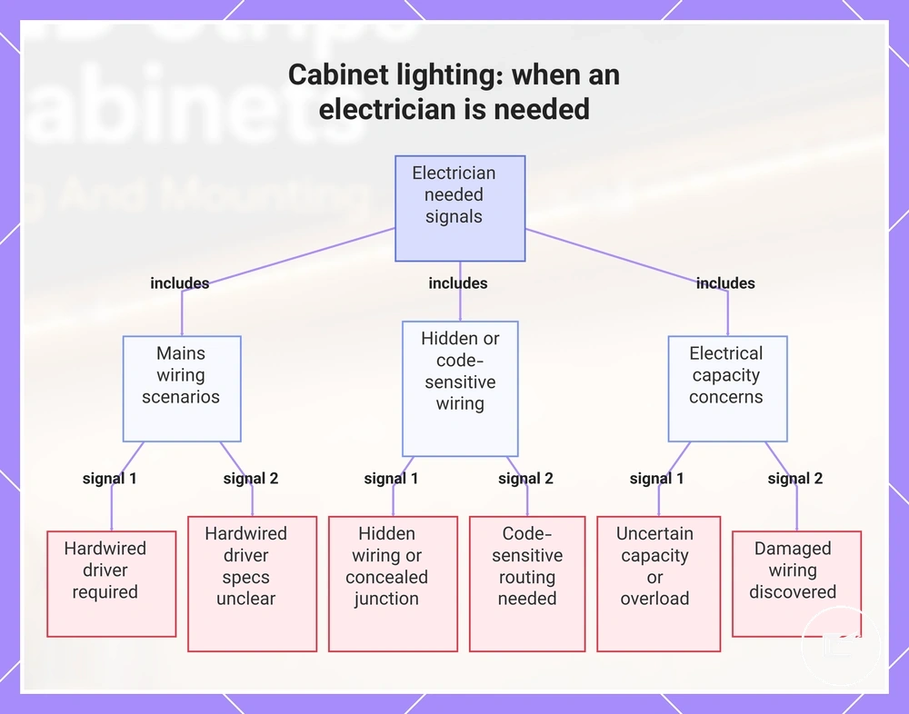
This chart identifies the key escalation signals that indicate an electrician is required for cabinet lighting installation.
Tools, Components, and Mounting Parts Needed
Tools, components, and mounting parts are the items that support power delivery, strip mounting, connections, and cable control during an under cabinet LED strip installation. Each part serves a specific installation role, so the list should stay focused on function rather than product selection. Identifying the required components before mounting can reduce compatibility issues, loose cable routing, or mounting adjustments later in the process.
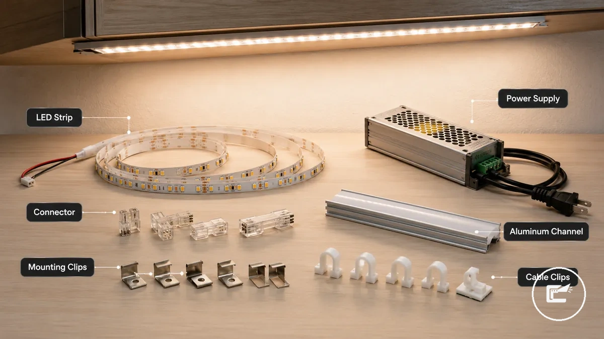
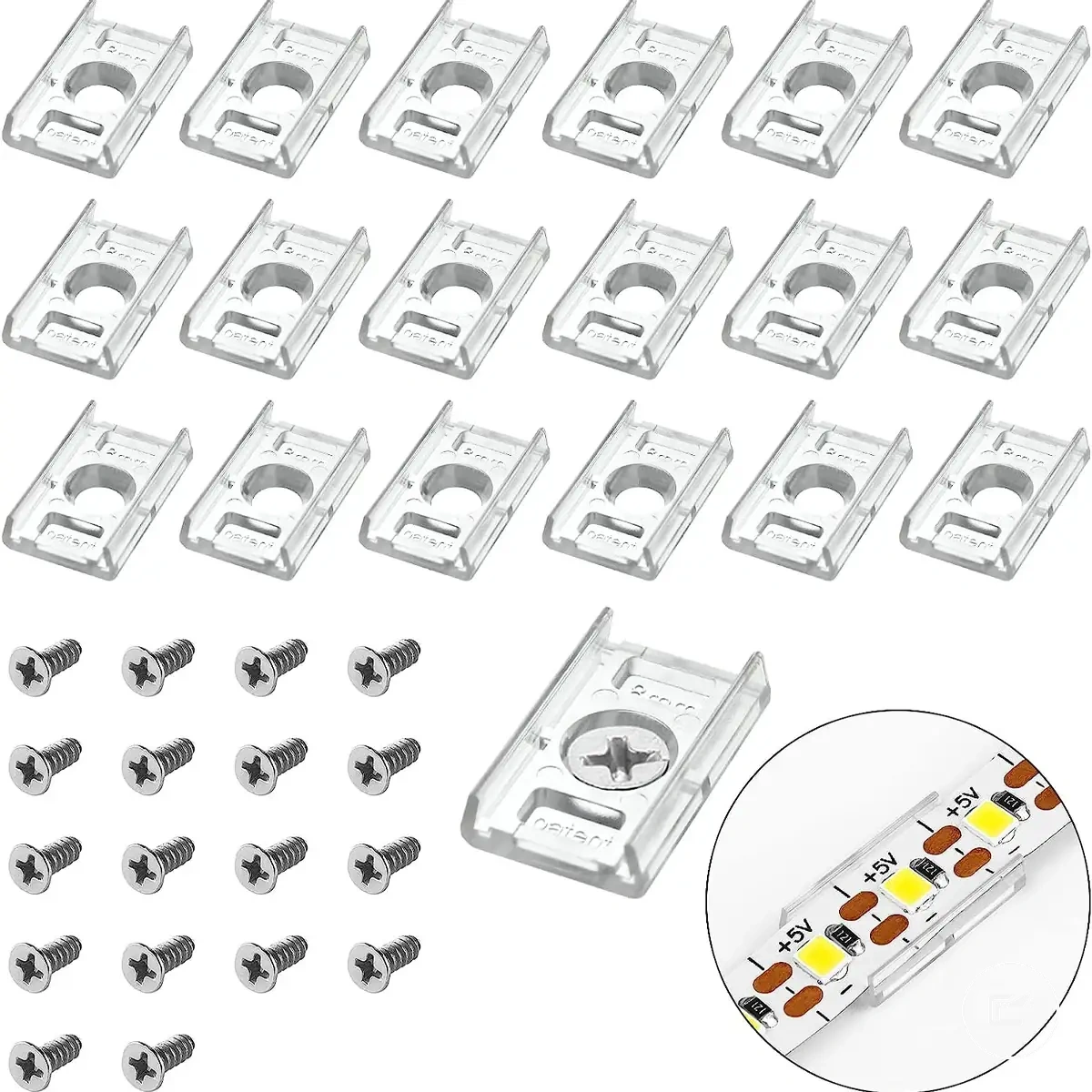
An LED strip and power supply form the core installation system. Connectors, extension cable, and cable clips help manage routing and connection points. Adhesive tape, mounting clips, aluminum channel, diffuser cover, cleaner, measuring tape, and scissors support surface preparation, placement, and fit where applicable.
Component selection depends on installation conditions. Mounting clips or an aluminum channel may be useful when extra support is preferred beyond adhesive tape alone, while extension cable accessories may help when the power supply location creates a longer cable route. Before choosing parts, review power and connector planning to confirm voltage, connector, and compatibility requirements.
| Component | Installation role | When it matters | Caution |
|---|---|---|---|
| LED strip | Primary light source | Required for the light run | Compatibility depends on the power system |
| Power supply | Provides operating power | Needed when the strip requires external power | Voltage compatibility should be confirmed |
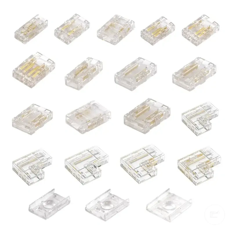
| Connector | Joins strip sections or components | Useful when direct connections are needed | Connector fit may vary by strip type |
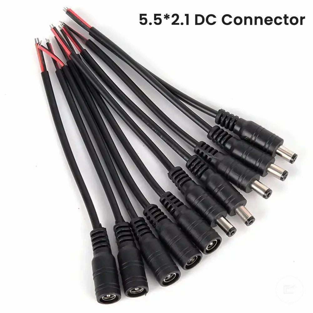
| Extension cable | Extends the cable route | Helpful when power access is farther away | Confirm compatibility before use |
| Adhesive tape | Supports strip mounting | Works best on a clean surface | Surface condition can affect adhesion |
| Mounting clips | Adds mechanical support | Useful when extra retention is preferred | May require drilling depending on installation |
| Aluminum channel | Supports strip placement and protection | Useful for a cleaner mounted run | Fit depends on available cabinet space |
| Diffuser cover | Covers the mounted strip | Often paired with an aluminum channel | Should match the selected channel |
| Cable clips | Controls cable routing | Useful for visible cable runs | Placement may affect future access |
| Cleaner | Prepares the cabinet surface | Helpful before adhesive mounting | Surface should be dry before installation |
| Measuring tape | Supports layout planning | Useful before cutting or mounting | Check measurements before installation |
| Scissors | Used where cutting is applicable | May be needed during strip preparation | Cut only where the strip design allows |
Planning Strip Position, Length, and Power Route
Planning under cabinet LED strip lights starts with deciding where the strip sits on the cabinet underside, how far it runs, and how the low voltage power route reaches it before mounting begins. Placement can affect light output, shadow visibility, and cable visibility. Early planning can also reduce mounting adjustments and connector changes after installation starts.
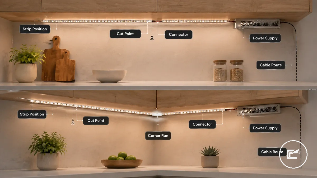
For under cabinet LED strip lighting, front placement may direct more light toward the work surface, while middle or rear placement can change how light spreads across nearby surfaces. Strip length should follow the planned cabinet underside run, and each connector should remain reachable within the installation layout. The power supply location should also support a practical cable route before mounting begins.
- Check whether the strip will be mounted near the front, middle, or rear of the cabinet underside.
- Measure the planned strip length and confirm any intended cut point before installation.
- Verify that the connector can reach the next connection point without excessive strain.
- Choose a power supply location that remains accessible after mounting.
- Plan the cable route so the low voltage cable path stays organized and visible sections are limited where practical.
- Review longer runs for voltage drop risk and confirm that the planned layout remains suitable.
A straight cabinet run is often easier to plan because the strip, connector, and cable route follow a single path. Corner layouts or multi-cabinet runs may require additional attention to connector reach, direction changes, and cable routing between sections. Before finalizing the layout, review power and connector planning to confirm that voltage, connector selection, and installation requirements remain aligned.
Front Edge, Middle, and Rear Placement
Choosing a position for under cabinet LED strip lights affects task lighting, glare, shadowing, and strip visibility during installation. Front edge, middle, and rear placement create different light effects on the cabinet underside and nearby surfaces, and the result can vary with cabinet lip depth, diffuser use, and counter finish.
| Placement | Light Effect | Visibility | Glare Risk | Cabinet Condition |
|---|---|---|---|---|
| Front Edge | May direct more light toward the work surface | Strip visibility can increase when the cabinet lip is shallow | May be more noticeable without a diffuser | Can suit cabinets with a deeper lip that helps conceal the strip |
| Middle | Can provide a more balanced light pattern across nearby surfaces | Strip visibility may be moderate | Glare risk can vary with diffuser type and viewing angle | May suit cabinets where balanced light distribution is preferred |
| Rear | May place more light toward the backsplash area | Strip visibility can be reduced in some layouts | Glare may be less noticeable from common viewing positions | Can work when cabinet depth and surface reflection support the layout |
A diffuser can soften the appearance of individual light points, while cabinet lip depth can influence whether the strip remains visible from normal viewing angles. No single placement is correct for every installation because cabinet dimensions, counter reflectivity, and diffuser configuration can change the lighting outcome.
Power Supply Location and Low Voltage Cable Path
Planning a power supply location starts with choosing a reachable position and a low voltage cable route that remains accessible after installation. For under cabinet LED strip lights, the power supply, connector direction, and cable path should be reviewed before mounting so cable reach, visibility, and future access can be checked without placing unnecessary strain on connections.
The power supply location should support practical access, ventilation, and cable management along the cabinet underside. A plug-in power supply or driver may be easier to inspect when it remains reachable, while concealed placement should still allow access for testing or adjustment when needed.
- Confirm that outlet access allows the plug-in power supply to remain reachable.
- Choose a power supply or driver location that remains accessible after mounting.
- Check that extension cable length is suitable for the planned cable route.
- Verify that connector direction matches the strip layout and cable path.
- Use cabinet gaps only when they provide a practical route without excessive cable strain.
- Review strain relief at connection points to help limit cable tension.
- Check that hidden cable sections remain accessible for inspection and adjustment when needed.
If the cable route passes through cabinet gaps or behind visible surfaces, cable reach, heat conditions, and connector access may influence the final layout. Avoid routing plans that depend on concealed mains wiring changes or inaccessible connections, as this subsection focuses only on low voltage installation planning.
Mounting LED Strips, Clips, or Diffuser Channels
Mounting LED strips, clips, or diffuser channels starts after planning is complete and depends on surface preparation, alignment, and the selected support method. A clean surface, accurate measuring, and consistent positioning can help reduce peeling risk and keep the strip run straight. The mounting method should match the cabinet surface and installation conditions rather than follow a universal approach.
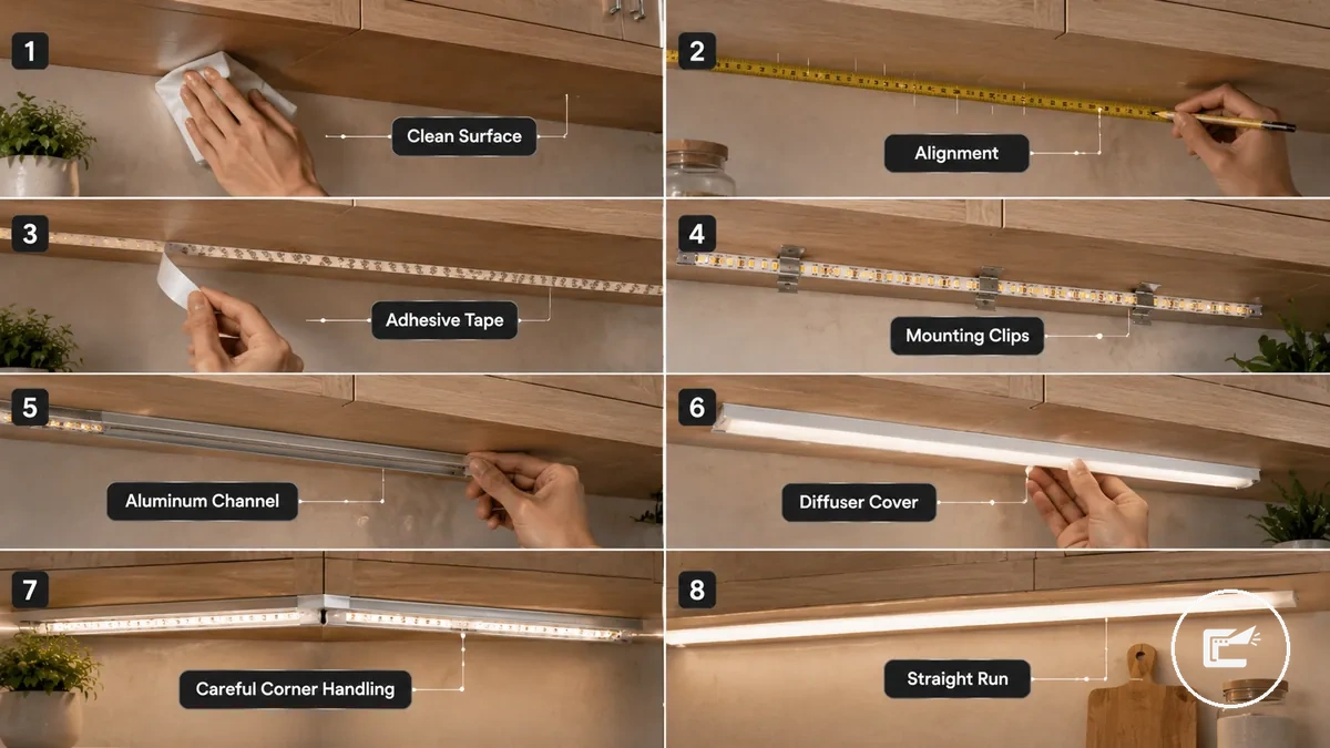
Mounting LED Strips, Clips, or Diffuser Channels involves choosing between adhesive tape, mounting clips, or an aluminum channel with a diffuser cover. Adhesive tape may suit smooth cabinet surfaces, while mounting clips or a channel can provide additional support when surface conditions, strip weight, or installation layout require it. Alignment, pressure time, and straightness should be checked throughout the mounting process.
- Clean the cabinet underside and allow the surface to dry so adhesive tape or mounting hardware can contact the surface more consistently.
- Measure and mark the strip run before attachment so alignment can be checked and adjusted before mounting begins.
- Position the strip along the marked path and apply adhesive tape with even pressure when the mounting method relies on adhesion.
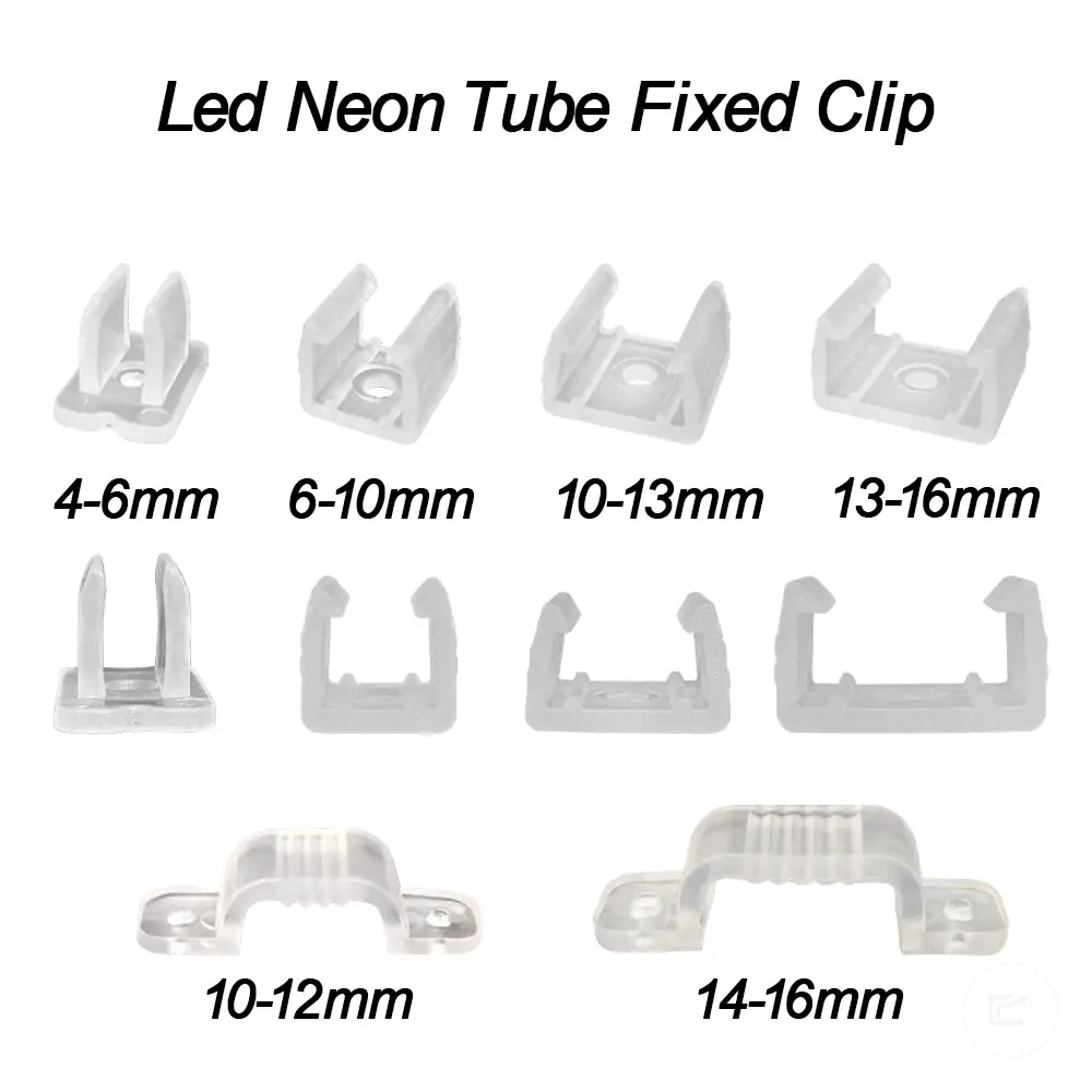
- Secure mounting clips or install an aluminum channel when additional support or strip protection may be beneficial for the installation.
- Fit the strip into the channel and add the diffuser cover when the channel design supports that configuration, helping maintain a neat light run.
- Guide the strip carefully around corners so alignment remains consistent and the strip is less likely to lift or shift during use.
- Leave suitable spacing around the strip or channel when heat conditions may affect mounting performance, then verify straightness before continuing to later installation stages.
If adhesive tape is applied to a surface that is not fully prepared, peeling or misalignment may occur more easily after mounting. Checking alignment before full pressure time is completed can make small adjustments easier than repositioning the entire strip run later.
Preparing the Surface and Measuring the Run
Preparing the surface and measuring the run starts with cleaning, drying, and marking the cabinet underside before mounting begins. Surface preparation helps assess adhesion conditions, while measuring supports alignment, strip length accuracy, and channel fit. These steps should be completed before attaching the strip, mounting clips, aluminum channel, or diffuser cover.
- Clean the cabinet underside when dust, grease, or residue is present so the mounting surface can provide more consistent contact for adhesive tape or mounting hardware.
- Allow the surface to dry completely when moisture is present so adhesion conditions are less likely to be affected during mounting.
- Measure the planned strip run and aluminum channel length before attachment so alignment and fit can be checked in advance.
- Mark the intended strip path when measurements are confirmed so the light run can remain straighter during mounting.
- Check strip cut marks against the measured run so length adjustments can be planned before attachment.
- Verify clearance for the strip run, aluminum channel, and diffuser cover when cabinet features may affect fit so mounting components can be positioned more accurately.
If the cabinet underside has a rough surface texture, adhesion performance may vary and mounting clips may become a more suitable support method. Checking alignment before full pressure time is applied can make small adjustments easier than repositioning the strip after attachment.
Using Adhesive Tape or Mounting Clips
Using adhesive tape or mounting clips starts with assessing the cabinet underside, strip weight, and mounting conditions before attachment. Adhesive tape may be sufficient for under cabinet LED strip lights when the mounting surface is smooth and the installation places limited load on the strip run, while mounting clips can add mechanical support when conditions are less favorable.
The support method depends on surface texture, heat exposure, weight, and adjustment needs:
- Adhesive tape: May suit smooth cabinet underside surfaces when strip weight is low and consistent surface contact is possible.
- Mounting clips: Can provide additional mechanical support when the surface is rough, textured, or less suitable for adhesive contact.
- Heat exposure: Higher heat conditions may affect adhesive performance, making clips a useful support option in some installations.
- Strip or channel weight: Heavier strip runs or added channel weight may benefit from mechanical support beyond adhesive tape alone.
- Removal risk: Mounting clips can reduce reliance on adhesive when future adjustment or repositioning may be needed.
For a low voltage installation, the support method should be evaluated alongside the power supply, connector position, mounting approach, and cable route so the strip remains supported without creating unnecessary strain on the cable path or connection points. :contentReference[oaicite:0]{index=0}
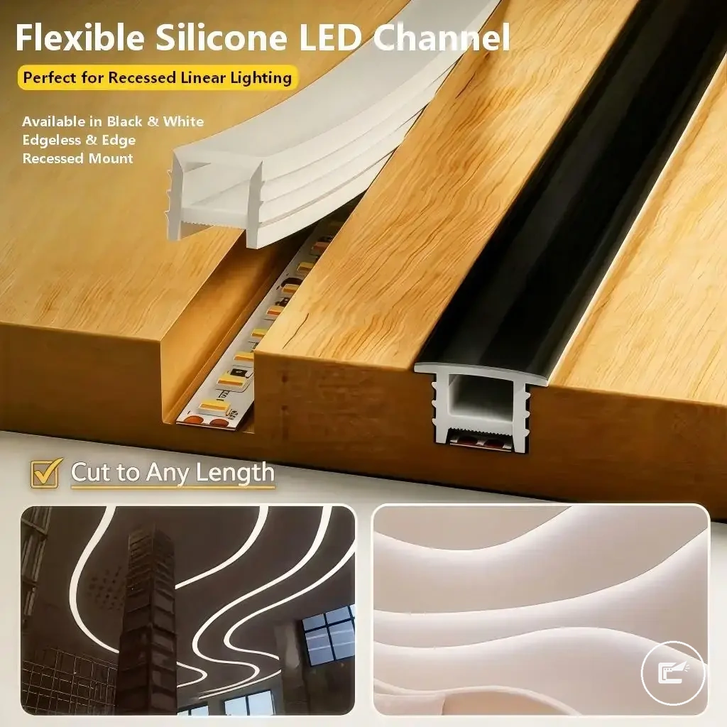
Installing Aluminum Channel and Diffuser Cover
Installing an aluminum channel and diffuser cover starts with positioning the channel on the cabinet underside so under cabinet LED strip lights can follow a straighter mounting path. An aluminum channel can provide strip protection and support light diffusion, while the diffuser cover can soften visible light points depending on diffuser fit, channel depth, strip brightness, and cabinet clearance.
- Position the aluminum channel along the planned strip run so channel depth and cabinet clearance can be checked before fixing.
- Secure the channel with mounting screws or clips when the mounting surface and installation conditions support that method, helping maintain channel alignment.
- Insert the under cabinet LED strip lights into the channel so the strip sits evenly without placing unnecessary strain on the low voltage connector or cable route.
- Check that the power supply connection, connector position, and cable route remain accessible before closing the channel.
- Fit the diffuser cover onto the channel so the cover aligns correctly and does not interfere with nearby cabinet features.
- Test the strip after installation to confirm the diffuser fit, light diffusion, and channel placement remain suitable for the installation.
Compared with exposed strip mounting, an aluminum channel can provide additional strip protection and a more controlled mounting path. Heat spread and light output may vary by channel material, diffuser type, strip brightness, and available cabinet clearance, so results are not identical in every installation. :contentReference[oaicite:0]{index=0}
Connecting the Power Supply and Testing the Light Run
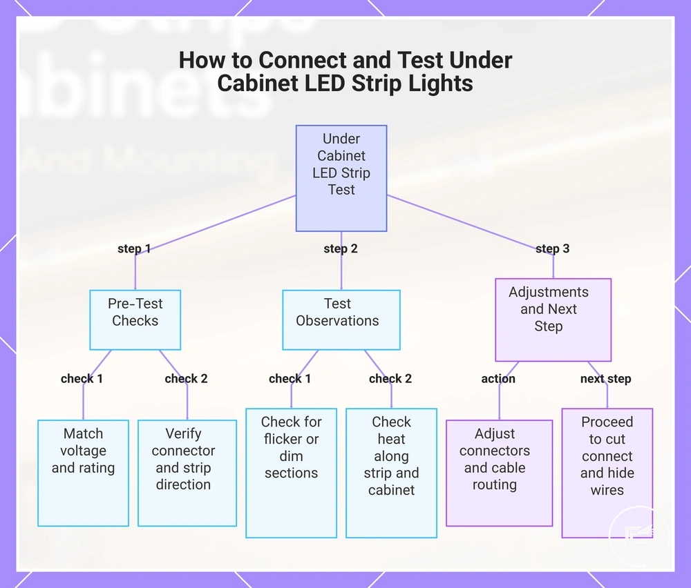
Connecting the low voltage power supply and testing the light run starts with confirming voltage, power rating, and connector orientation before finalizing the installation. Testing while the strip remains accessible helps detect dim sections, flicker, or heat issues without concealing connections under the cabinet.
Ensure that under cabinet LED strip lights, the power supply, connectors, and cable route are correctly aligned. Check the strip direction and any controller or dimmer if present to maintain proper operation along the cabinet underside.
Perform a preliminary connection test. Observe the strip for flicker, partial illumination, or uneven brightness. Adjust connector orientation, cable path, and power supply placement to reduce strain and ensure consistent light output. For the next stage, proceed to cut connect and hide wires to finalize cable management.:contentReference[oaicite:0]{index=0}
- Confirm that the power supply voltage and rating match the strip's low voltage requirement for the planned cabinet underside run.
- Verify connector orientation and strip direction along the cabinet underside to avoid reversed polarity or misalignment.
- Temporarily connect the strip to the power supply and any controller or dimmer for testing without final mounting.
- Observe for flicker, dim sections, or uneven light output along the cable path.
- Check heat along the strip and nearby cabinet surfaces to ensure safe operation during the initial test.
- Adjust connectors or cable routing to minimize strain and maintain proper alignment before finalizing mounting and concealment.:contentReference[oaicite:1]{index=1}
This chart shows the step-by-step process of connecting the power supply, testing the LED strip for issues, and final adjustments before installation.
Tidying Low Voltage Cables After the Test Fit
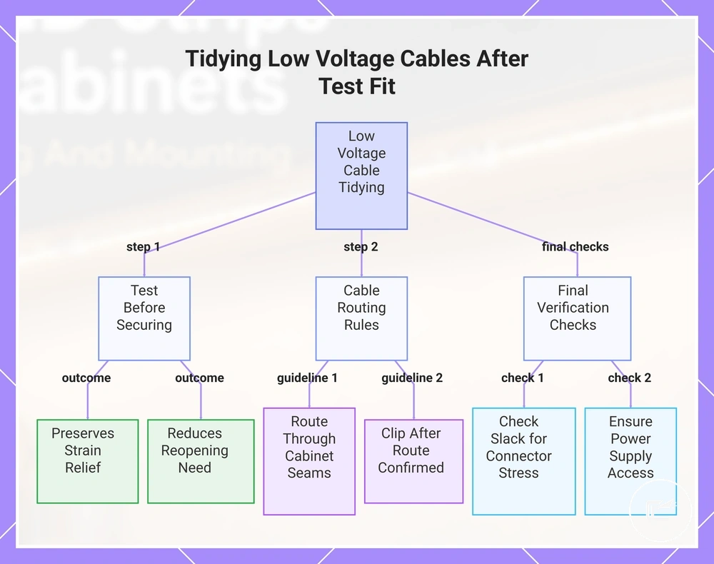
Tidying low voltage cables starts after under cabinet LED strip lights have been tested and the final cable route is confirmed. Testing first helps identify connection issues before cables are secured. This approach can preserve strain relief, maintain access to components, and reduce the need to reopen a finished installation.
When visible cables remain along the cabinet underside, route them through cabinet seams and corner paths where the cable path stays organized and accessible. Use cable clips only after the final wire route is confirmed. If additional cable management is needed, the next stage may involve how to cut connect and hide wires without changing the tested layout.
Check that extension cable slack is sufficient to avoid connector stress during normal use. The power supply, connector, and any service point should remain reachable if future inspection is needed. Avoid securing cables tightly near heat-producing components, and confirm that the low voltage cable route does not place strain on connections or mounting hardware.
If cable clips, cable slack, connector position, power supply access, and corner routing all remain suitable after the test fit, the installation can move to final cable organization with fewer adjustments expected later.:contentReference[oaicite:0]{index=0}
The products below are useful examples for comparing available options. Before buying, check that the compatibility criteria, key features, and product details match your needs.
This chart shows the main steps and checks for tidying low voltage cables after testing under cabinet LED strip lights, including testing first, routing guidelines, and final verification.
Under Cabinet LED Strip Installation Mistakes to Avoid
Common installation mistakes can cause visible symptoms such as flicker, dimming, or peeling. Recognizing these errors before or during installation helps prevent poor light output, connector stress, and cable strain on under cabinet LED strip lights. Understanding how symptoms connect to causes and preventive steps supports a more reliable mounting on the cabinet underside.
Key mistakes include poor adhesion, weak mounting support, incorrect power supply, voltage drop, connector mismatch, bad strip placement, overbending, heat buildup, and cable strain. Each can affect the strip’s performance and light output if not addressed during the initial installation process.
Use the table below to link each mistake with its likely cause, a safe check, and prevention strategy. This helps identify potential issues without repeating the full installation sequence or turning this into a troubleshooting guide.
| Problem | Likely cause | Safe check | Prevention |
|---|---|---|---|
| Loose strip or peeling adhesion | Poor surface preparation or weak mounting support | Check cabinet underside cleanliness and strip attachment | Clean the surface and use adequate support before mounting |
| Flicker or unstable light output | Incorrect power supply or connector error | Verify voltage, power supply rating, and connector fit | Confirm compatibility and test before final mounting |
| Dimming at strip ends | Voltage drop | Observe brightness along the strip run | Plan strip length and power requirements appropriately |
| Uneven lighting or glare | Bad placement on cabinet underside | Review strip position and light distribution | Position strip for intended illumination area |
| Strip damage or intermittent operation | Overbending or cable stress | Inspect bends and connection points | Avoid sharp bends and excessive cable tension |
| Heat-related dimming | Poor heat spacing or trapped heat | Check for restricted airflow around the strip | Allow spacing and avoid covering heat-sensitive areas |
| Connector instability | Cable strain | Inspect cable route and points of tension | Provide strain relief and secure visible cables |
If a symptom persists after basic checks, consider how to fix installation problems. :contentReference[oaicite:0]{index=0}
Weak Adhesion and Poor Surface Preparation
When a loose strip or peeling symptom appears, weak adhesion is often linked to cabinet surface conditions rather than a single cause. Grease, dust, moisture, texture, or excess warmth on the cabinet surface can reduce adhesive contact. This mistake may create a poor hold during cabinet lighting installation and increase the risk of strip movement over time.
Check these local causes and prevention points:
- Surface material: A textured cabinet surface may provide less adhesive contact than a smoother surface.
- Grease or dust: Residue on the cabinet surface can weaken adhesion and increase peeling risk.
- Cleaner residue: Remaining cleaner film may reduce adhesive grip if the surface is not fully clear.
- Moisture and drying time: A damp surface may increase the likelihood of a loose strip after mounting.
- Adhesive pressure: Uneven pressure during installation can leave sections with weaker contact.
- Strip weight: Heavier strip runs or channels may place additional stress on adhesive attachment points.
- Clip support: Supplemental clips can help when strip weight, surface texture, or mounting conditions create additional load.
- Humidity and heat buildup: Environmental conditions may affect adhesion performance depending on the installation area.
Weak adhesion does not always indicate the same cause. Surface material, moisture levels, heat buildup, and strip weight can interact differently across installations, so prevention should focus on the specific cabinet surface condition rather than assuming a single source of failure. :contentReference[oaicite:0]{index=0}
Wrong Power Supply, Voltage Drop, and Connector Errors
When dimming, flicker, partial lighting, or no light appears after installation, a power supply issue, voltage drop, or connector error may be the cause. This mistake does not always come from the same source, so the symptom should be matched to the most likely cause before making changes to the installation.
| Problem | Likely cause | Safe check | Prevention |
|---|---|---|---|
| Flicker | Loose connector or controller mismatch | Check connector fit and controller compatibility | Confirm connections before final mounting |
| Dimming | Voltage drop or insufficient wattage | Observe brightness across the full strip run | Match power requirements to the installation layout |
| Partial lighting | Connector error or overloaded connection | Inspect connection points along the strip | Avoid placing excessive load on a single connection |
| No light | Voltage mismatch, polarity direction issue, or disconnected connector | Verify voltage compatibility and connector orientation | Check polarity and connection alignment before testing |
| Uneven performance | Long runs contributing to voltage drop | Compare brightness from one end of the run to the other | Plan longer runs with power requirements in mind |
Not every symptom points to the same cause. Voltage drop, connector error, controller mismatch, and power supply limitations can create similar results, while heat buildup, cable strain, adhesion issues, or bad placement may contribute to separate installation problems. If the symptom remains after these checks, review how to fix installation problems. :contentReference[oaicite:0]{index=0}
Bad Placement, Bending, and Heat Buildup
When glare, shadows, visible dots, or uneven light quality appear after installation, bad placement, sharp bends, or heat buildup may be the cause. This mistake can place physical stress on under cabinet LED strip lights and may affect performance over time, depending on strip type, bend radius, channel fit, and ventilation conditions.
Prevention checks include:
- Bad placement: Position the strip to reduce glare, shadows, and visible dots on the intended work surface.
- Sharp bends: Maintain the minimum bend radius recommended for the strip to reduce corner stress, connector error risk, and cable strain.
- Diffuser clearance: Ensure the diffuser and strip have suitable clearance so light distribution is not restricted.
- Cramped channel: Avoid tight channel conditions that may contribute to heat buildup or reduce light quality.
- Blocked heat path: Keep channel ventilation unobstructed so heat can dissipate more effectively.
- Adhesion support: Check that bends and corners do not create lifting forces that may weaken adhesion or lead to a loose strip.
Bad placement, bend stress, and blocked heat paths do not always create the same symptom. Heat buildup, voltage drop, connector error, and physical strain can interact differently across installations, so prevention should focus on the specific condition affecting cabinet lighting performance. :contentReference[oaicite:0]{index=0}